Environmental Engineering Reference
In-Depth Information
1.0
2.0
COP low volume flow
COP high volume flow
0.9
1.8
Q
o
low volume flow
Q
o
high volume flow
0.8
1.6
0.7
1.4
0.6
1.2
0.5
1.0
0.4
0.8
0.3
0.6
0.2
0.4
0.1
0.2
0.0
0.0
110
115
120
125
130
135
140
145
150
155
160
Generator heating inlet temperature / °C
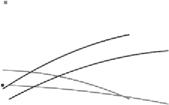
Figure 5.51
Influence of external mass flow in the generator on cooling power and COP
For the indirectly driven generator of the DACM, the limit values for the inner tube
diameter are presented in Figure 5.52 for the transition from slug to annular flow and
Figure 5.53 for the transition from bubbly to slug flow. The maximum value of the
tube diameter for maintaining slug flow increases with increasing surface tension and
decreases with liquid density. The minimum tube diameter for preventing bubbly flow
increases with the desired vapour volume flow and decreases with increasing surface
tension. The equations derived byChisholm, Taitel and others are summarized in Jakob
(2006). Slug flow usually occurs within tubes that have an inner diameter ranging from
5 to 41mm (Jakob, 2006). All calculations were done for a generator with 19 tubes.
46.0
annular flow
45.0
X
s
= 28%
44.0
X
s
= 32%
43.0
slug flow
X
s
= 36%
42.0
41.0
40.0
90
95
100
105
110
115
120
125
130
135
140
145
150
Mean internal generator temperature T
G
/ °C
Figure 5.52
Maximum inner tube diameter as a function of generator temperature for the transition
between slug and annular flow


Search WWH ::

Custom Search