Information Technology Reference
In-Depth Information
Once the docking pattern has been computed, one step of the trajectory defor-
mation algorithm described in Section 17.3 is applied by changing the right hand
side of boundary conditions (17.12) by a vector making the final configuration of
the current trajectory move toward the docking configuration.
17.6
Experimental Results
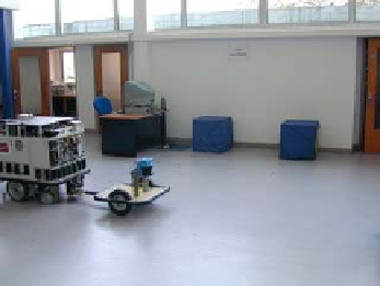
We have implemented and tested this method on a real robot. We present the results
gathered after experiments in realistic scenarios.
A common scenario for a truck with a trailer is to park the trailer along an un-
loading platform. That is the final position of the trailer is defined relatively to the
unloading platform. We have reproduced this scenario with Hilare 2 towing a trailer.
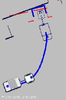
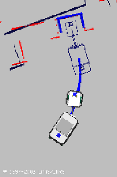
Fig. 17.6
A docking task: the robot is required to reach the unloading platform the shape of
which is represented in bold: the
docking pattern
. The laser perception is shifted with respect
to the map: it means that the robot is poorly localized. However, the robot is able to detect
the
docking pattern
and to deform the reference trajectory in order to avoid obstacles and to
dock at the unloading platform. The docking task is executed with respect to the perception
and not with respect to the map


Search WWH ::

Custom Search