Information Technology Reference
In-Depth Information
Fig. 17.7
The position and the shape of the unloading platform have been changed compared
to figure 17.6. The unloading platform has been shifted to the right and it has been enlarged
by 0.2 m. The docking configuration is computed as the configuration where the
docking
pattern
best fits the unloading platform
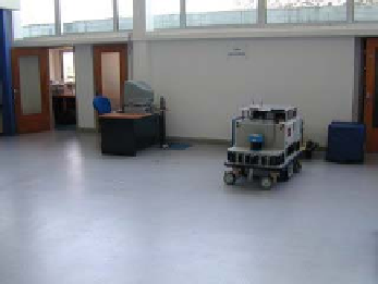
The trailer is equipped with a laser range sensor. In this experiment the landmarks
are straight line segments. The
docking pattern
can be composed of any number of
segments.
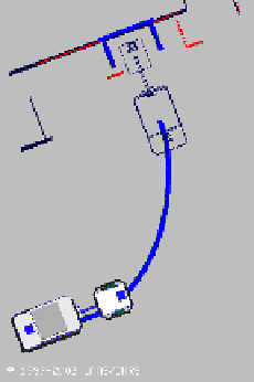
17.6.1
Bad Localization
Figure 17.6 represents this scenario. We see that the map does not perfectly match
the perception. This is due to a bad localization of the robot. The docking configura-
tion is anyway computed with respect to the sensor perception. The robot detects the
unloading platform. Then it deforms the trajectory in order to dock at the unloading
platform and to avoid obstacles. Let us notice that in this experiment the robot does
not need to stop to compute the docking configuration nor to deform the trajectory.
It is true as long as the docking configuration is close to the end of the trajectory.


Search WWH ::

Custom Search