Environmental Engineering Reference
In-Depth Information
(a)
(b)
TiO
2
ZnO:Al
Pt
Cu
2
O
Au
FTO
500nm
(c)
(d)
0
0
-1
-1
-2
-2
-3
2
-3
2
0
-4
0
-4
-2
-2
-5
-5
-4
-4
-6
-6
-6
-6
-8
-7
-8
-7
0
5
10
15
20
0
5
10
15
20
Time (min)
Time (min)
-8
-8
0.25
0.30
0.35 0.40 0.45 0.50 0.55
0
0.1
0.2
0.3
0.4
0.5
E
(V) versus RHE
E
(V) versus RHE
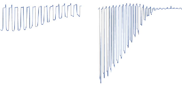
FIGURE 3.5
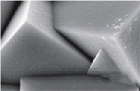
(a) Schematic presentation of the electrode structure. (b) Scanning electron micrograph
showing a top view of the electrode after ALD of 5 × (4 nm ZnO/0.17 nm Al
2
O
3
)/11 nm TiO
2
followed
by electrodeposition of Pt nanoparticles. (c) Current-potential characteristics in 1 M Na
2
SO
4
solution
under chopped AM 1.5 light illumination for the bare Cu
2
O electrode, (d) for the as-deposited 5 × (4 nm
ZnO/0.17 nm Al
2
O
3
)/11 nm TiO
2
. The insets show respective photocurrent transient for the electrodes
held at 0 V versus RHE in chopped light illumination with N
2
purging.
Source
: Reproduced with permis-
sion from Paracchino et al. [32]. (See color insert.)
photostability for water reduction (Fig. 3.5d). A photocurrent of 7 mA cm
−2
was obtained at 0.25 V versus RHE for the protected Cu
2
O electrode.
Importantly, 78% of photocurrent retention was achieved on the protected
Cu
2
O after 20-min illumination (Fig. 3.5d, inset). The Faradaic efficiency of
H
2
generation is close to 100%, indicating the photocurrent decay was not
due to the degradation of the photoactive materials. The decay was attrib-
uted to the presence of Ti
3+
traps in the TiO
2
layer. Since the Fermi level of
TiO
2
in the dark is close to the water reduction potential, the electrons were
not readily injected into the electrolyte and accumulated in the protective
layer as long-lived Ti
3+
states. This study demonstrated an effective strategy
to stabilize Cu
2
O by coating protective metal oxide layers.


Search WWH ::

Custom Search