Environmental Engineering Reference
In-Depth Information
• Intake stroke
: Fuel and air are brought into the cylinder through intake valve(s) as the pis-
ton moves down the cylinder [from top dead center (TDC) to bottom dead center (BDC)].
• Compression stroke
: As the piston moves up the cylinder (from BDC to TDC), the intake
valves are closed and gases are compressed, thus increasing the temperature and pressure.
• Expansion stroke
: The combustion of fuel and air creates CO
2
, H
2
O, and other products
at high temperature and pressure. The high pressure pushes the piston down the cylinder
(TDC to BDC). This is the only stroke in which work is extracted from the engine.
• Exhaust stroke
: The exhaust valves open and the piston moves up the cylinder (from BDC
to TDC), pushing the combustion products to the exhaust system. After the exhaust stroke
is complete, the intake stroke begins again, signifying the start of another cycle.
Although all four-stroke engines operate on this same basic cycle, there are two distinctly different
variations. These two variations, the SI and CI engine, differ in how the fuel is introduced and how the
fuel and air mixture is ignited and burned. These are shown visually in Figure 10.7. This includes SI
engines that use a premixed fuel-air mixture and exhibit a homogeneous propagating flame. CI com-
bustion is based on a diffusion flame with nonpremixed combustion. The SI and CI engine are dis-
cussed in the following two sections, along with effects of fuels on their performance and emissions.
10.2.2 Si E
nginES
Inside of the combustion chamber of the engine, the correct fuel-air mixture must be present to
initiate and sustain combustion in a controlled manner over a portion of the cycle. In SI engines, as
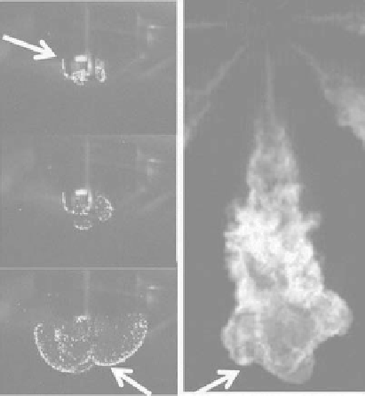
SI kernel development
lean methane-air
mixture
CI: combusting diesel
spray plume-21%
Oxygen
7 ms
Spark
plug
Injector tip
12 ms
34 ms
Flame boundary
FIGure 10.7
SI and CI combustion images. SI combustion exhibits a homogeneous propagating flame of the
premixed air-fuel mixture, with CI combustion utilizing diffusion flame combustion based on fuel injection
into a hot environment of ambient gases. Images were acquired in the Michigan Technological Univeristy opti-
cally accessible CV combustion vessel. (From Johnson, S., et al.,
Proceedings of the ASME 2010 International
Combustion Engine Division Fall Technical Conference
ICEF 2010, September 12-15, 2010; San Antonio,
TX and Nesbitt, J., et al.,
Proceedings of the ASME 2010 International Combustion Engine Division Fall
Technical Conference ICEF 2010,
September 12-15, 2010, San Antonio, TX.)