Biomedical Engineering Reference
In-Depth Information
In this study, the current intensity was fixed, so that the
Lorentz force induced displacement remained identical for all
conditions. On the other hand, the overlap between the current
and the oscillating gradients was systematically varied, resulting
in different amounts of loss of phase coherence. As such, these
results demonstrate that the observed signal loss is predominantly
due to the intravoxel dephasing resulting from the spatially inco-
herent displacement of the gel rather than the bulk displacement
of the wire itself. Indeed, the signal loss from the bulk displace-
ment itself is virtually undetectable as shown in the first image in
Fig. 14.6
, where only one cycle of overlap was used.
Furthermore, since the duration of one cycle of oscillating
gradients is only 4 ms, these results also demonstrate that a tem-
poral resolution on the order of milliseconds can be achieved with
the LEI technique, which represents a dramatic improvement -
at least two orders of magnitude - as compared to conventional
BOLD fMRI.
5.2. In vivo
Experiments
Figure 14.7
shows a representative functional activation map for
Experiment 1, in which three cycles of gradient oscillations and
three synchronized electrical pulses were used, overlaid on high-
resolution
T
1
-weighted images of the forearm. Highly significant
activation was found along the median nerve across subjects. The
time course averaged over the activated region shows a systematic
signal decrease of (4. 4
0. 7)% during the stimulation periods
(
Fig. 14.8a
). The transitions between rest and stimulation peri-
ods exhibit no delay, in contrast to what is typically observed in
conventional BOLD fMRI studies, which are limited by a hemo-
dynamic delay of 3-6 seconds.
±
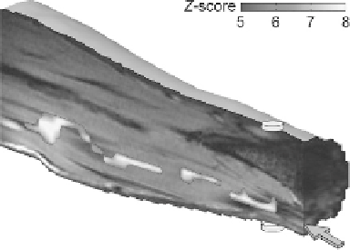
Fig. 14.7. Activation map showing the effect of neuroelectric activity in vivo in the
human median nerve. The activation was obtained using three cycles of gradient oscilla-
tions and three electrical pulses synchronized with the negative gradient lobes (Exp. 1),
and is overlaid on a stack of coregistered anatomical images. The discs represent the
electrodes placed on the dorsal (top) and ventral (bottom) sides of the wrist. The arrow
points to the median nerve.