Biomedical Engineering Reference
In-Depth Information
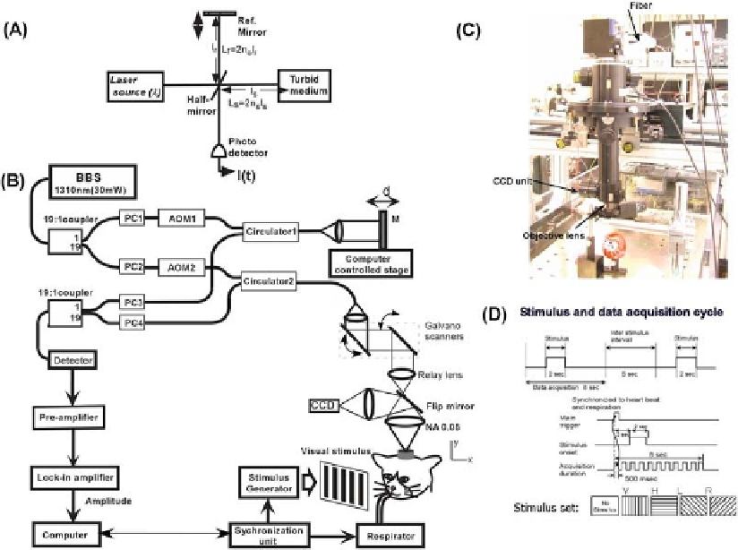
Fig. 6.7. A schematic of the basic principle of OCT (
A
) and the experimental system used (
B
) along with a picture of the
probe unit (
C
) and a schematic of the scanning paradigm (
D
). In the figure (
B
), the abbreviations denote: BBS - Broad
Band Source, AOM- Acousto-Optic Modulator, PC - Polarization Controller, M - Mirror and O - Objective lens. (
See
Color
Plate)
the cortex optically and obtain depth-resolved reflectivity maps.
The experimental system used in our studies and other details are
described in Appendix 2.
5. Functional
Imaging with OCT
(fOCT)
Prior to doing functional imaging with OCT, we performed in
vivo optical intrinsic signal imaging with the exposed cortical sur-
face of cat visual cortex (
Fig. 6.8A
) at a wavelength of 607 nm.
The stimulus set was identical to the one used in fOCT. It con-
sisted of four differently oriented gratings and a blank screen used
as a control (see detailed protocol in Appendix 2).
Figure 6.8B
shows the thresholded difference maps obtained when horizontal
and vertical grating visual stimuli were presented to the cat. Dark
and bright regions indicate the activated regions for horizontal
and vertical gratings, respectively.