Graphics Programs Reference
In-Depth Information
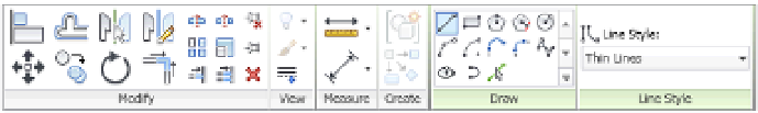
Figure 16.4
The Detail line
toolset
Line Style
This panel includes a drop-down menu that allows you to choose a line style in
which to produce the linework in this view. The drop-down menu has all the default Revit line
styles as well as any custom ones you might have made for your project or to accommodate
office standards. The active line will be the one displayed in the drop-down window before it's
expanded.
New line styles can be added at any time in the project, and many offices find it necessary to
add custom line styles beyond the thin, medium, and wide ones available in Revit out of the
box. To add more styles or to just see the complete list, choose Additional Settings from the
Manage tab and select Line Styles (Figure 16.4). For more information about creating your
own custom line styles, refer to Chapter 4, Configuring Templates and Standards.
Draw
The Draw panel contains a number of geometry tools to draw within the active view.
The tools allow you to create lines, boxes, circles, splines, ellipses, and arcs. The last tool in the
bottom row is the Pick tool. This tool allows you to select a line previously drawn or portion of
a model element (say an edge) and add linework on top of the existing shape.
Modify
The Modify panel has several tools that you can use to modify any of the linework
already placed within the view. The larger tools, from left to right, are Align, Offset, Mirror
(axis), Mirror (line), Move, Copy, Rotate, and Trim.
Using the Linework Tool
Although not part of the Annotate tab, the Linework tool helps you make your detail
composition more legible. Default settings for object styles and line weights will manage most
of a view's composition automatically, but you sometimes need to adjust a line or two to clarify
a detail. The Linework tool allows you to modify the edges of model elements in a view-specific
context. Note that this tool is not available in a drafting view because it works only on model
elements.
To use the Linework tool, switch to the Modify tab in the ribbon, locate the View panel, and
click Linework. This will add the familiar Line Style selector panel at the end of the ribbon.
Simply choose the line style you want to assign, and then select an edge of a model element.
The edges you pick can be almost anything: cut lines of walls, families, edges of floor slabs, and
so on. Selecting the edge of an element will change the default line style to the style you have
chosen. To return an edge to its original line style, use the Linework tool again, but select <By
Category> from the Line Style drop-down list.
You can also choose to remove lines using this tool. By selecting the <Invisible Lines> line
type, you can make some edges disappear. Use this method instead of covering unwanted lines
with masking regions.
Another great use of the Linework tool is to indicate the edges of overhead ceilings or floors
in a floor plan view. To accomplish this task, set the Underlay property of the active view to the
level where the ceiling, floor, or roof is associated. If necessary, set the Underlay Orientation to
Reflected Ceiling Plan. Start the Linework tool, select an overhead line style, and then pick any
Certification
Objective