Graphics Programs Reference
In-Depth Information
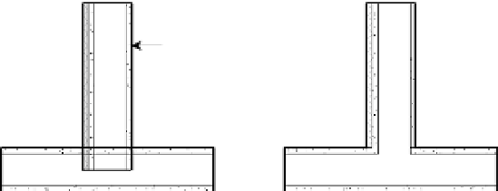
Priority 1 is the highest and 5 is the lowest. A layer that has a priority of 1 will cut through any
other layer with a lower priority (2, 3, 4, or 5). A layer with priority 2 will cut through layers
with priority 3, 4, or 5, and so on. In Figure 12.4, layers with the same priority clean up when
the two intersecting walls are joined. Notice the way the finish layers don't join on the right
side of the vertical wall because one has a priority 4 and the other is priority 5.
Figure 12.4
layers with the
same priority
clean up when
joined.
5
5
4
1
Material
Associating a material to a wall layer provides graphic (color, cut/surface pat-
terns, and render appearance), identifiable (mark, keynote, description, and so on), and
physical characteristics (for analysis purposes) for each wall layer. Using material takeoffs,
you can calculate quantities of individual materials used in wall assemblies throughout
your project. Keynoting and material tagging functionality are also supported through
wall layers and are discussed in greater detail in Chapter 18, “Annotating Your Design.”
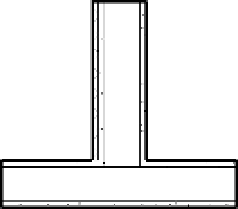
A material definition also affects cleanup between layers of joined walls. If the prior-
ity of the layers is the same and the material is the same, the software cleans up the join
between these two layers. If the priority of the layers is the same but the materials are
different, the two layers are separated graphically with a thin line. In Figure 12.5 the
structure layer of one of the joined walls was simply changed from Metal - Stud Layer to
Metal - Stud Layer 2.
Figure 12.5
two layers with the
same priority but
different materials.
The separation
between the two
layers is indicated
with a thin line.
1
Thickness
This value represents the actual thickness of the material. Note that the
membrane layer is the only layer that can have a thickness of zero.
Wraps
Wall layers rarely end with exposed edges at wall ends or wall openings, win-
dows, or doors. This option allows a layer to wrap around other layers when an opening
or wall end is encountered. Figure 12.6 illustrates the layer wrapping of the outer wall
layer based on the closure plane defined in the window family. Layer wrapping will be
covered in greater detail later in this chapter.