Graphics Programs Reference
In-Depth Information
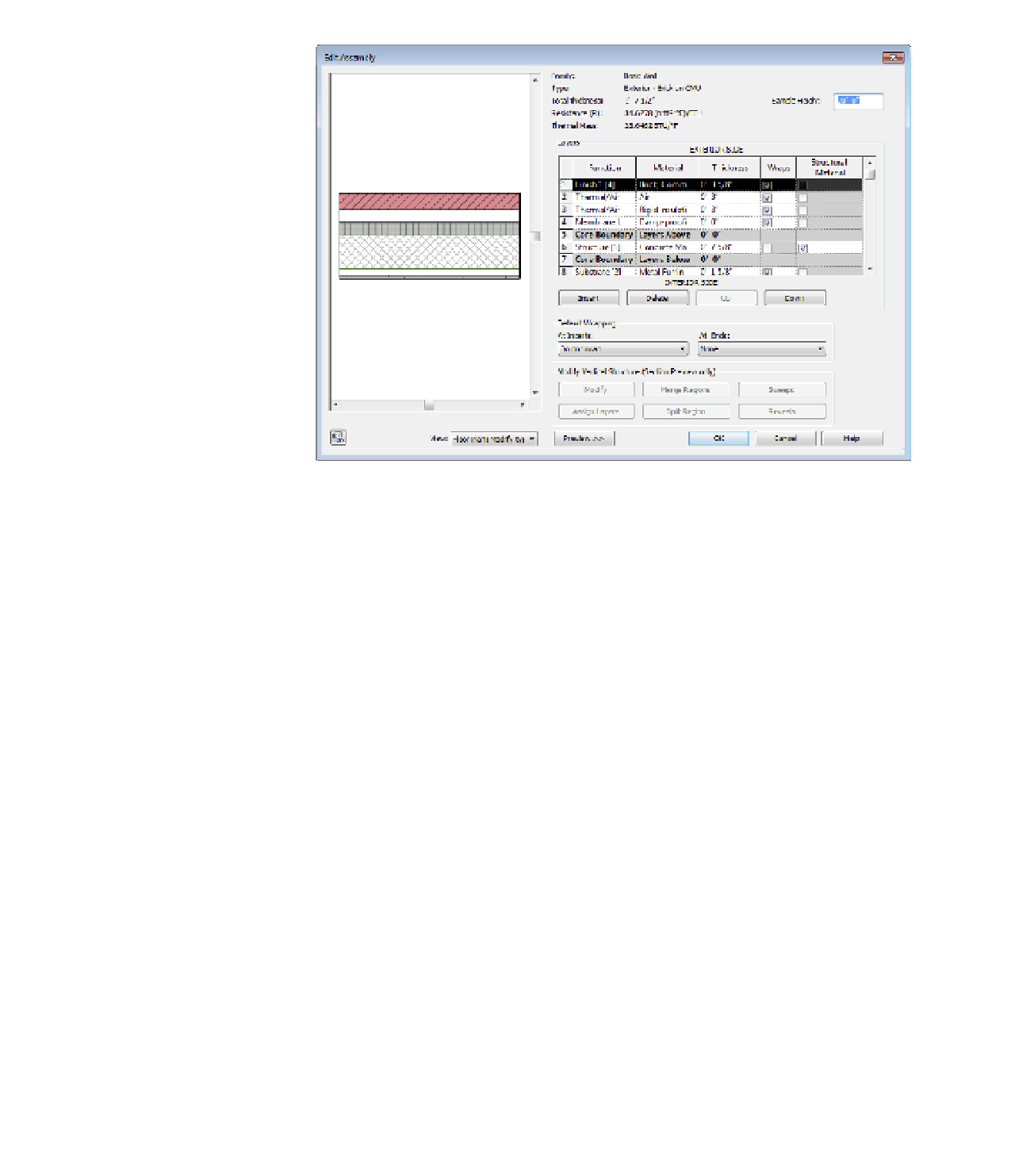
Figure 12.3
The edit
assembly
dialog box lets
you define the
construction
layers of a wall
type.
Layers Table
The Layers table is where you add, delete, move, and define layers of the wall
structure. Each wall layer is represented as a separate row of information. Two of the rows are
gray, representing the core boundaries of the wall, which will be discussed in greater detail
later in this chapter in the section “Creating a Wall Core.” The table is divided into five col-
umns (Function, Material, Thickness, Wraps, and Structural Material):
Function
This column provides six choices for wall layer functions that relate to the
purpose of the material in the assembly. Each of these functions defines a priority that
determines how it joins with other walls, floors, and roofs. Note that the numeric priority
is more important to understand than the name of the function itself.
◆
Structure [1] defines the structural components of the wall that should support the
rest of the wall layers. This function gives the highest priority to a wall layer and
allows it to join with other structural layers by cutting through lower-priority layers.
◆
Substrate [2] defines continuous board materials such as plywood, particle, and gyp-
sum board.
◆
Thermal/Air [3] defines the wall's thermal insulation layer and/or an air gap.
◆
The Membrane Layer is a zero-thickness material that usually represents vapor
prevention.
◆
Finish 1 [4] specifies a finish layer to use if you have only one layer of finish.
◆
Finish 2 [5] specifies a secondary, weaker finish layer.
With the exception of the Membrane Layer, which has no priority assigned, all the other layers
have a priority value from 1 to 5. These priorities determine how to clean up the intersections
between various layers when two or more walls are joined. The principle is simply explained: