Graphics Programs Reference
In-Depth Information
In the main list within the Lines tab, any line patterns defined in your Revit project can be
assigned to a specific CAD-based linetype. The default linetype definitions file is included with
Revit, but it can be changed with the command buttons above the line patterns list. The default
setting for exporting line patterns is Automatically Generate Linetype, which will replicate the
graphic pattern but will not integrate well with any other CAD software if the exported files
require additional modification by the recipient.
patterns
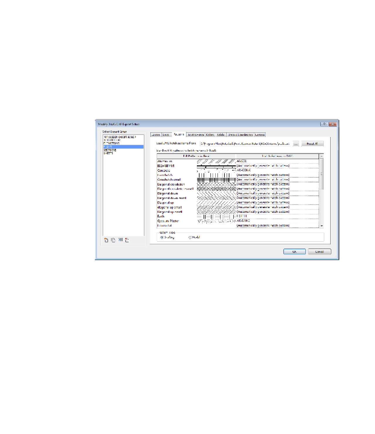
As with lines, the exporting of fill patterns can be completely customized. Switch to the Patterns
tab (Figure 7.25), and you will see similar options to specify a default CAD-based pattern file as
well as the ability to assign Revit fill patterns to respective hatch patterns.
F igur e 7.25
fill patterns
can be assigned
to CaD hatch
patterns.
Similar customizations can also be made for fonts in the Text & Fonts tab, and in the Colors
tab you can choose to either use specific layer-based color IDs or use the true color RGB values
assigned in your Revit project. Let's take a quick look at the remaining tabs and their importance.
Solids
In the Solids tab, you have the option to select either Polymesh or ACIS Solids for exporting
of 3D views. For cleaner solid geometry exporting, we recommend the ACIS Solids option;
however, this will likely result in larger file size upon export.
Units & Coordinates
One of the most important settings is Coordinate System Basis, which can be found in the
Units & Coordinates tab. This option will affect the ability of your exported files to be properly
aligned with other project files. Refer back to Chapter 6 for more information on using shared
coordinates.