Graphics Programs Reference
In-Depth Information
Model patterns
are used to convey real-world dimensional patterns to represent a material,
whereas
drafting patterns
are intended for symbolic representations. For example, a model
pattern is used to show a brick pattern in 3D and elevation views, whereas a brick drafting
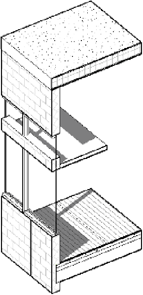
pattern is used to represent the material in plan and section. Figure 4.15 shows how concrete
masonry units (CMUs) are represented with a running bond pattern (model) as well as a
crosshatch (drafting). To display cut patterns in a 3D view, a section box must be enabled and
adjusted to intersect a model element.
Figure 4.15
The Cmu wall has
both a drafting
pattern (cut) and
a model pattern
(surface) defined.
cut pattern
surface pattern
Model patterns have specific behaviors that are not dependent on any view. The scale you
establish in a model pattern will always be that size, regardless of the view scale. In the example
shown in Figure 4.15, the surface of the CMU wall displays a block pattern that measures
16˝ × 8˝ (400 mm × 200 mm). If you were to change the view scale, the pattern would appear
larger or smaller but it would always measure the same. With a drafting pattern, the opposite is
true: The pattern adjusts with the view scale, so the pattern looks identical in all scales.
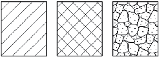
Fill patterns are also created as one of two types: simple or custom. Figure 4.16 illustrates
some examples of each option.
Figure 4.16
from left to right: a
simple fill pattern,
a simple fill pattern
with the crosshatch
option selected, and a
custom fill pattern