Environmental Engineering Reference
In-Depth Information
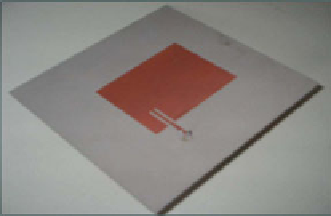
(a)
(b)
Fig. 5.16 a
geometric configuration of the microstrip antenna.
b
photograph of the used
antenna [12]
1
10
h
w
−
1
/
2
ε
eff
=
ε
r
,
sub
+
ε
m
2
+
ε
r
,
sub
−
ε
m
2
+
(5.35)
where
ε
r
,
sub
is the relative permittivity of the antenna substrate;
h
is its thickness;
w
and
L
are the width and the length of the radiating patch, respectively; and
ε
m
is
the relative permittivity of the medium in which the antenna radiates [see Fig. 5.16]
[65, 70].
Considering the previous formulas, when the antenna radiates in free space, then
ε
m
equals 1 (which is the relative permittivity of air), and the antenna will resonate
at a specific frequency,
f
air
res
. On the other hand, when a different material is placed in
front of the antenna,
ε
m
changes, and
f
res
will change accordingly. The direct impli-
cation is that the resonant frequency is closely related to the dielectric characteristics
of the medium in which the antenna radiates.
As for the practical evaluation of
f
res
, it can be measured from the minimum of
the magnitude of
S
11
(
f
)
, which is given by


Search WWH ::

Custom Search