Environmental Engineering Reference
In-Depth Information
be chosen to cover the major harmonic components in the current, e.g. the 3rd, 5th and 7th
harmonics.
Since
K
i
has the capability of dampening oscillations, it can be chosen to be large so that the
impedance at low frequencies is dominantly resistive. As a result, the robust droop controller
for R-inverters shown in Figure 20.2(b), which is discussed in Chapter 19, can be adopted
to generate the voltage reference
v
r
. The combination of both strategies is able to solve the
three main problems associated with parallel-operated inverters, i.e. sharing accuracy, voltage
regulation and voltage THD, with a compact controller.
20.2 Experimental Results
This strategy was verified with a laboratory set-up consisting of two single-phase inverters
illustrated in Figure 20.1, which were controlled by dSPACE kits and powered by separate 42
VDC power supplies. The values of the inductors and capacitors were 2
.
35 mH and 22
μ
F,
respectively. The switching frequency was 7
5 kHz and the fundamental frequency of the
system was 50 Hz. The rated output voltage was 12 V RMS and
K
e
=
.
10. The inverters were
designed to have resistive output impedance with the current feedback
K
i
. The coefficients for
K
R
were chosen as
K
3
=
5. Due to the configuration of the hardware
set-up, the voltage for Inverter 2 was measured by the controller of Inverter 1 and then sent
out via a DAC channel, which was then sampled by the controller of Inverter 2. This brought
some latency but the effect was not noticeable. Inverter 1 was equipped with a synchronisation
unit. It was synchronised with Inverter 2 when its output was not connected to that of Inverter
2 and was ready to be connected at any time.
14,
K
5
=
10 and
K
7
=
2
.
20.2.1
1:1
Power Sharing
In this case, the droop coefficients were set as
n
1
=
0
.
8 and
n
2
=
0
.
8;
m
1
=
0
.
2 and
m
2
=
0
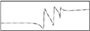
4 were chosen and the output
impedances of the inverters were resistive over a wide range of frequencies covering the
fundamental frequency, as can be seen from the Bode plots of the output impedances of both
inverters shown in Figure 20.3. Clearly, the impedances at the 3rd, 5th and 7th harmonic
.
2. Hence, it was expected that
P
1
=
P
2
.
K
1
=
4 and
K
2
=
12
10
Z
o1
Z
o2
8
6
4
2
0
135
90
45
0
−45
10
2
10
3
10
4
Frequency (rad/sec)
Figure 20.3
Bode plots of the output impedances of the inverters for 1 : 1 power sharing


Search WWH ::

Custom Search