Environmental Engineering Reference
In-Depth Information
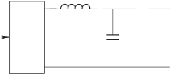
V
DC
-
+
u
f
i
i
o
v
o
L
CB
u
IGBT
H-bridge
PWM
C
AC bus
Figure 20.1
Single-phase inverter with a PWM block and an LC filter
of which the gain at frequency
h
is
K
h
with zero phase. It is almost 1 everywhere apart from
at the frequencies around the harmonics. This is equivalent to reducing the output impedance
of the inverter
ω
sL
+
K
i
Z
o
(
s
)
=
1
+
K
R
(
s
)
+
to
sL
K
i
ω
v
o
. The
at the frequency
h
. This helps improve the THD of the output voltage
1
+
K
h
damping factor
ξ
can be chosen as
ξ
=
0
.
01 to accommodate frequency variations and
h
can
v
o
i
-
K
i
K
R
(
s
)
-
u
v
r
(a) The controller discussed in Chapter 8 to improve voltage
THD
E
*
-
K
RMS
e
-
E
i
1
P
i
n
i
s
v
o
v
ri
Q
i
1
i
m
i
s
ω
i
t+
δ
i
*
ω
(b) Robust droop controller to generate the voltage reference
Figure 20.2
Robust droop control with improved voltage THD for R-inverters


Search WWH ::

Custom Search