Environmental Engineering Reference
In-Depth Information
Transformer
v
a
a
i
L
a
v
b
~
b
v
v
c
c
Q
1
Q
3
Q
5
Q
7
Q
9
L
L
L
L
C
V
DC
C
Q
4
Q
6
Q
8
Q
10
Q
2
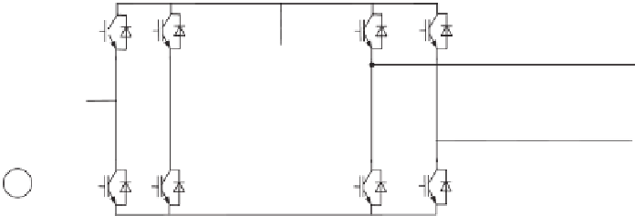
Figure 14.3
Single-phase to three-phase converter with a universal active power filter.
Source:
Cipriano
dos Santos
et al
. 2011
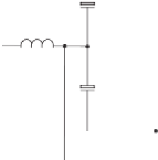
14.2 The Topology under Consideration
According to the analysis in Chapters 10-13, an independently-controlled neutral leg is able
to maintain a stable and balanced neutral point that is the mid-point of the DC link. This can
be applied to form a single-phase to three-phase converter with three independent phases.
Moreover, this neutral line can be shared with the single-phase supply to reduce the number
of power semiconductor switches needed. The resulting topology is shown in Figure 14.4.
Rectifier
Leg
Neutral
Leg
Phase
Leg
b
Phase
Leg
c
i
a
v
a
=v
a
Q
7
Q
1
Q
3
Q
5
C
N+
i
b
v
b
v
fb
b
L
N
V
DC
L
a
i
L
i
C
i
s
L
s
L
r
L
i
c
v
c
i
v
fc
c
i
r
C
N-
~
v
Q
2
Q
4
Q
6
Q
8
C
C
N
Figure 14.4
The single-phase to three-phase converter under consideration


Search WWH ::

Custom Search