Environmental Engineering Reference
In-Depth Information
to the motor. The current harmonics and low input power factor can be improved by adding
a boost converter between the rectifier and the inverter (Singh and Singh 2010), as shown
in Figure 14.1(b). Figure 14.1(c) shows another popular topology consisting of a controlled
single-phase full-bridge rectifier with a three-phase full-bridge inverter (Bose 2001; Kwak and
Toliyat 2005). Although it is able to provide a clean grid current that is in phase with the grid
voltage as well as high quality output voltage, it requires ten power semiconductor switches to
process the full power. For economic and reliable operation, it is better to reduce the number
of switches. One of the rectifier legs can be replaced with a split DC link to reduce the number
of switches (Lee and Kim 2007; Singh and Singh 2010), as shown in Figure 14.1(d). However,
it has some drawbacks, such as high output voltage distortion and large DC-link capacitors
(Blaabjerg
et al
. 1997; Lee and Kim 2007). For these conventional topologies, the full load
power needs to be processed by the converter, which increases the cost of the converter.
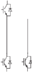
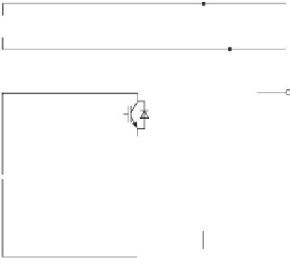
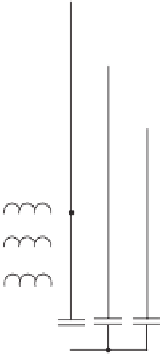
The topology shown in Figure 14.2 only processes partial load power because one phase
is powered directly by the supply (Machado
et al
. 2006). It takes advantage of the supply
voltage as the line-to-line voltage and generates another line to form a balanced three-phase
voltages. The three-phase converter in this topology acts as an active power filter to provide
the reactive and harmonic currents required by the load so that the supply current is clean
and in phase with the supply voltage. Note that the generated line voltage depends on the
load power. Another drawback is that no neutral line is available for unbalanced loads. The
topology shown in Figure 14.3 is another one with a single-phase to three-phase universal
active power filter (Cipriano dos Santos
et al
. 2011), where a controlled full-bridge rectifier
with four switches and a transformer are added to the topology shown in Figure 14.2. The
generated phase voltages are balanced and have the same voltage level as the supply voltage
but a transformer is needed and no neutral line is available for the operation of unbalanced
three-phase loads. Moreover, for these two topologies, there may be significant amount of
harmonics in the output voltage as well since no strategies are designed to obtain high power
quality under high power non-linear loads.
i
v
a
a
LL
~
v
v
b
b
v
c
c
Q
1
Q
3
Q
5
L
a
L
b
L
c
C
V
DC
C
a
C
b
C
c
Q
2
Q
4
Q
6
Figure 14.2
Line-interactive single-phase to three-phase converter.
Source:
Machado
et al.
2006


Search WWH ::

Custom Search