Biomedical Engineering Reference
In-Depth Information
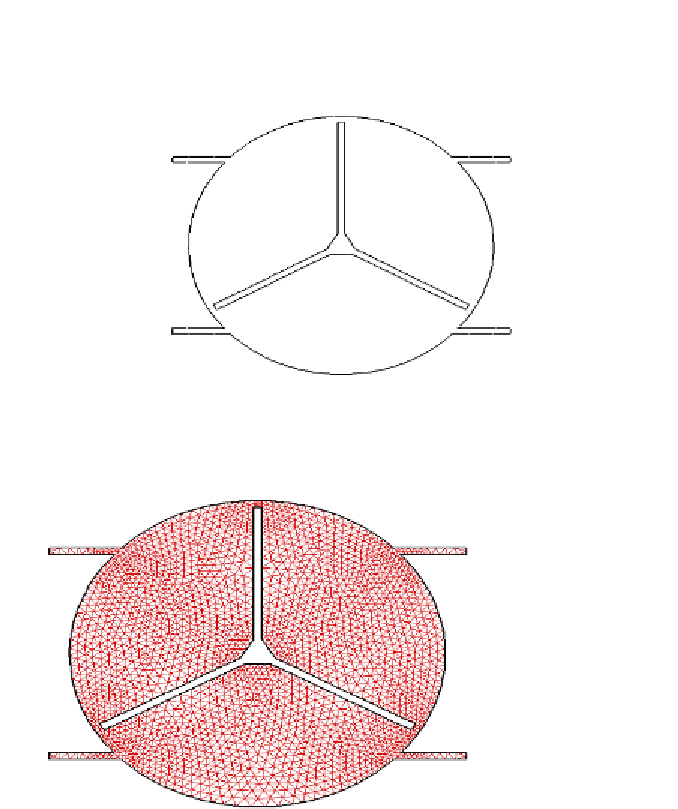
The experimental spindle has been modeled using FLUENT to determine
the pressures and velocities. The schematic of the spindle is shown in Figure
14.
Reproduced with permission. Copyright retained by Inderscience Publishers.
Figure 14. Schematic of the rotor.
Reproduced with permission. Copyright retained by Inderscience Publishers.
Figure 15. Mesh of the experimental rotor.
The grid for this geometry is shown in Figure 15. The grid has been
generated in GAMBIT. The grid is made of total 2200 points and triangular
mesh elements. The grid is clustered near the tip clearance and near the hub.
The inlet to the domain is based on the stagnation pressure and temperature
inlet BC while at the outlet the back-pressure of suction is applied. The fluid