Biomedical Engineering Reference
In-Depth Information
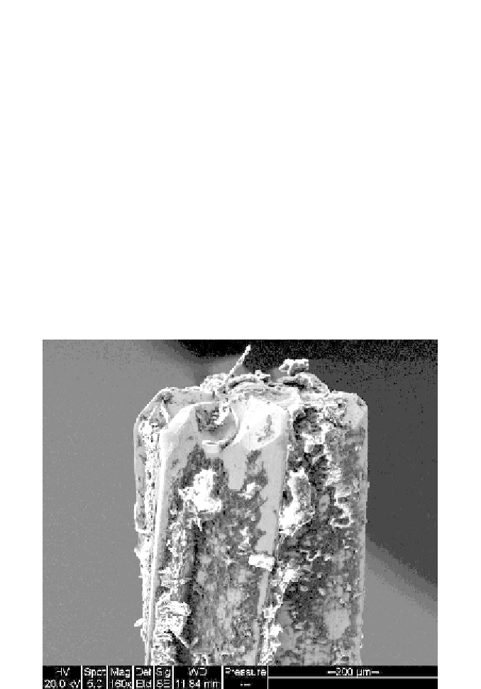
Figure 6 shows a magnified image of a coated cutting tool. The clearance
faces of the flutes of the cutting tool show adherent bone chips with finely
striated lamellae, as noted on the left hand side of the tool. Figure 7 shows a
magnified image of a coated cutting tool detailing the cutting edge and its
relationship to the adherent film of bovine femur showing fine striations of
lamellae generated at high strain rates.
4.3. Micromachining Results
The results of machining bovine femur at the microscale are compared to
the model described for primary chip curl during the primary stages of chip
formation. It should be noted that all results presented in Table 1 are for bone
machined in an aqueous saline environment. Table 1 shows the results for
biomachining using a variety of rake angles. It should be noted that bending of
the cutting tool produces a less acute rake angle when machining takes place.
However, the shear plane angle is increased and larger chips are produced.
Figure 6. Magnified image of the cutting tool showing cutting edges and adhered bone
material. Reproduced with permission. Copyright retained by Inderscience Publishers.