Biomedical Engineering Reference
In-Depth Information
curl the chip and as a consequence of this event, the following model is
presented. Previous treatments of chip curl analysis [5] have focused on chip
formation with a perfectly stiff cutting tool. However, during the machining of
bone it is observed that the cutting tool bends as it cuts [6]. This means that
primary chip curl models must account for deflection of the cutting tool by
bending during an orthogonal machining operation. Computational approaches
to modeling chip formation at the microscale have been attempted in recent
years by a number of researchers [7,8], who have used a molecular dynamics
simulation approach using a perfectly stiff cutting tool.
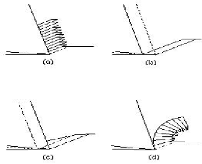
Figure 1. Instability during the formation of a chip during micromachining: (a)
segmented, continuous chip; (b) chip forming instability due to built-up edge; (c)
movement of a built-up edge to form a chip; (d) serrated, continuous chip curl.
Reproduced with permission. Copyright retained by Inderscience Publishers.
The generation of a transient built-up edge ahead of the cutting tool
between shearing events in a bulging-type of motion generates the shape of the
segment of the metal chip. This is shown in Figure 1c, with the built-up edge
forming the ‗shaded triangle' above the shear plane. If it is assumed that the
built-up edge does not ‗pass' under the tool edge, then the areas of the shaded
triangles in Figures 1b and 1c will be equal. The chip moves away from the
rake force in a manner shown in Figure 1d. The radius of chip curl can be
calculated by assuming that the built-up edge in transient and that the element
of the ‗bulged' material contains a small angle relative to the tool and
workpiece. This angle will inevitably change during the bending action of the
cutting tool. If we assume that the cutting tool moves from point A to point D
then the shear plane AC rotates to position HC as the built-up edge from