Environmental Engineering Reference
In-Depth Information
y
y
x
e
yI
M
bx
F
d
x
e
yII
z
F
d
F
z
z
M
b
y
F
d
F
z
F
z
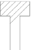
Abb. 5.2.
Biegemomente M
bx
, M
by
und Abstand zur Randfaser e
yI
, ey
II
Für einfache Profile lauten die Flächenträgheitsmomente:
y
4
S
d
I
Kreisprofil
(5.1)
x
64
x
x
3
b
h
I
Rechteckprofil
(5.2)
x
12
y
e
yI
y
Beim Kreis- und Rechteckprofil sind die Abstände zur Rand-
faser gleich, so dass e
yI
= e
yII
= e
y
wird und das Widerstands-
moment sich aus
W
(5.3)
ergibt. Beim T-Profil liegt keine Symmetrie um die x-Achse
vor. Die Abstände zur Randfaser sind unterschiedlich zu be-
rücksichtigen.
I
e
b
x
y
x
x
y
e
yII
3
3
B
H
b
h
yI
I
B
H
b
h
e
T-Profil
(5.4)
e
yI
y
x
3
2
2
1
B
H
b
h
x
x
e
mit
(5.5)
b
yI
2
B
H
b
h
e
H
e
und
(5.6)
yII
yI
e
yII
y
B
W
I
e
W
I
e
wird
;
(5.7)
bI
x
yI
bII
x
yII
Für beliebige Abstände von den Hauptträgheitsachsen ergibt sich die Biegespan-
nung
σ
bx
zu
M
bx
V
y
(5.8).
bx
I
x


Search WWH ::

Custom Search