Hardware Reference
In-Depth Information
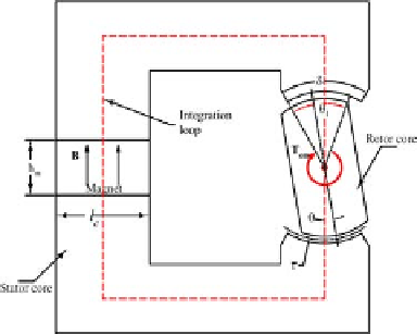
about its shaft, but there is no armature winding and current on the rotor.
It can be stated, referring to the permanent magnet with the characteristic
showninFigure4.28,the
fl
ux density going through the magnet is constant
at B
r
. Therefore, the
fl
ux φ
m
produced by the magnet is constant. Neglecting
the leakage
fi
eld, the airgap
fl
ux φ
g
is same as φ
m
, as explained in section 4.1.6.
Therefore, φ
g
is constant and independent of the rotor position,
φ
g
= φ
m
= B
r
A
m
= B
r
l
m
l
c
, (4.48)
where, l
m
and l
c
and A
m
are the thickness, the width, and the cross-section
area of the magnet, respectively; see Figure4.6.Supposetherotorisrotated
by an angle of θ
◦
where
|
θ
|
<
δ
2
as illustrated in Figure 4.29.
Figure 4.29: Moving the rotor by a small angle
The effective angle coupling the surfaces of the stator and the rotor is
θ
1
= δ−
|
θ
|
. (4.49)
Therefore, the reluctance of this magnetic circuit,
m
(θ), is formed by the
reluctances of the two airgaps, that is,
m
(θ)=2
g
(θ),
(4.50)
and
g
(θ)=
g
µ
0
r
·
(δ−
|
θ
|
)
·
l
m
,
(4.51)
where, r is the average radius of the airgap. Using the discussions presented
in section 4.1.4, the magnetic energy of whole system is
W
g
= w
g
V
g
=
1
µ
0
B
g
V
g
=
1
µ
0
(
φ
g
A
g
)
2
V
g
1
µ
0
(
B
r
l
c
l
m
r(δ−
|
θ
|
)l
m
)
2
[r(δ−
|
θ
|
)l
m
g]
=
(4.52)
gl
m
µ
0
r(δ−
|
θ
|
)
=
1
(B
r
l
c
)
2
2
(B
r
l
c
)
2
l
2
m
=
g
(θ).