Hardware Reference
In-Depth Information
If the center of the rotor is not aligned with the center of the stator, i.e.,
θ= 0, then the magnetic
fi
eld in the airgap generates an EM torque to make
these centers aligned. This torque can be calculated by using virtual work
method [69]. The principle of this method is based on the fact that the EM
energy of the motor varies with rotor position and this variation can induce
an EM torque T
r
(θ) acting on the rotor. This torque can be expressed as a
function of θ,
(
(B
r
l
c
)
2
−
gl
µ
0
0 < θ <
δ
2
r(δ−θ)
2
,
T
r
(θ)=−
dW
g
dθ
= −
1
2
(B
r
l
c
)
2
l
2
m
d
g
(θ)
=
dθ
(B
r
l
c
)
2
r(δ+θ)
2
, −
δ
2
< θ < 0.
(4.53)
Such a torque cannot be explained directly from the concept of the Am-
pere's force as there is no current-carrying conductor in the motor. From
equation 4.53, it is the variation in reluctance that can be considered as the
cause of this kind of torque in an electric motor. Hence, this torque is normally
called the reluctance torque.
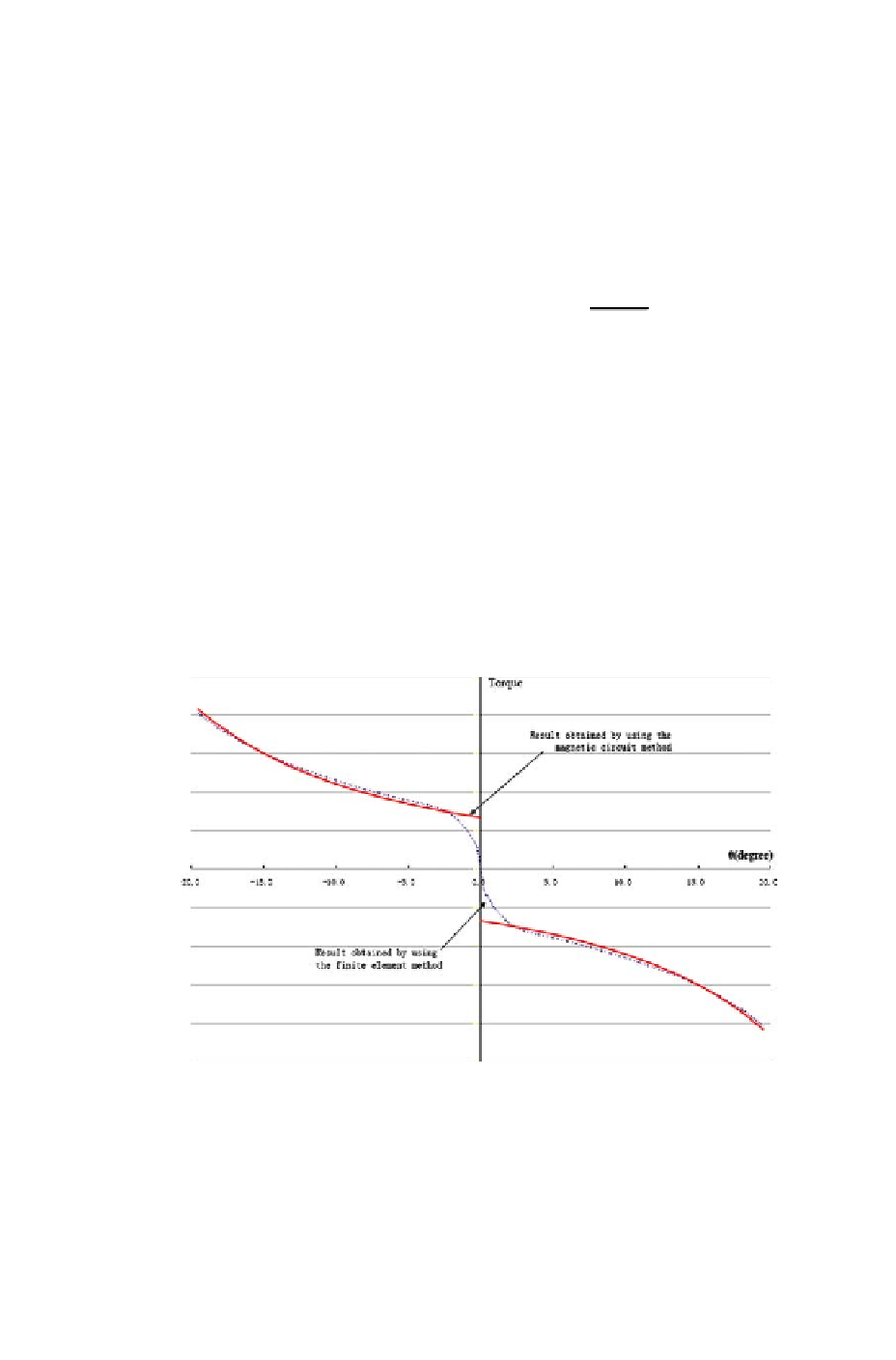
The torque as a function of θ, which is obtained using the equation above,
is shown in Figure 4.30. Using virtual work and extremum methods, it is
not difficult to prove that the torque at equals zero. If the rotor is rotated
alittlefromthepositionθ =0
◦
by external disturbance, it can be deduced
from equation 4.53 that the rotor will return to the original position when the
disturbance disappears. Therefore, the position θ=0
◦
is a stable point for the
motor shown in Figure 4.29.
gl
m
µ
0
Figure 4.30: Reluctance torque
Figure 4.30 also shows the same torque calculated using the
fi
nite element
method, which is an accurate numerical method widely used in electromagnetic