Hardware Reference
In-Depth Information
20
0
−20
−40
−60
−80
−100
10
1
10
2
10
3
10
4
10
5
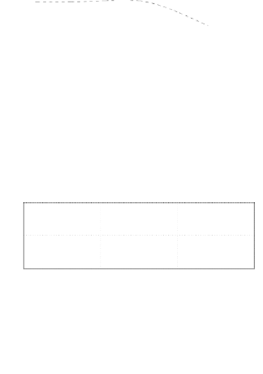
Figure 3.87: Sensitivity (solid line) and complementary sensitivity (dashed
line) transfer functions.
50
0
−50
10
2
10
3
10
4
10
5
Frequency (rad/sec)
0
−90
−180
10
2
10
3
10
4
10
5
Frequency (rad/sec)
Figure 3.88: R(s) frequency response. At below f
h
,
|R(s)| > 1. At above f
h
,
|R(s)| < 1
If we define
C
VP
= C
V
(1 + C
M
P
m
), (3.170)
then the implementation of the DMS structure based controller is similar to
that of the parallel structure.
Because of very small phase lag of the PZT actuator in the low frequency
range, the simple lag-lead compensator (equation 3.149) for the VCM and a
lag compensator for the PZT actuator (equation 3.150) also work for the DMS
structure after some adjustments of the control parameters. For the plant in
the previous example, we choose the lag-lead compensator such that the zero