Hardware Reference
In-Depth Information
20
0
−20
−40
−60
−80
−100
10
0
10
1
10
2
10
3
10
4
10
5
200
100
0
10
0
10
1
10
2
10
3
10
4
10
5
Frequency (rad/s)
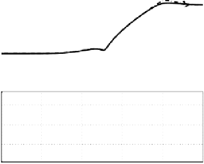
Figure 3.22: Sensitivity transfer function corresponding to Figure 3.20. Solid
line: notch based design. Dashed-line: phase stable based design.
160
140
120
100
80
60
40
10
0
10
1
10
2
10
3
10
4
10
5
10
6
0
−100
−200
−300
10
0
10
1
10
2
10
3
10
4
10
5
10
6
Frequency (rad/s)
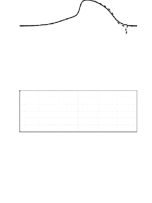
Figure 3.23: Shock transfer function corresponding to Figure 3.20. Solid line:
notch based design. Dashed-line: phase stable based design.
are shown in Figures 3.20-3.23 for the phase stable design of compensator for
the plant model used in previous sections. The controller is described by the
equation 3.11 with phase stable compensator described by equation 3.24; the
controller is designed to achieve crossover frequency f
v
= 1800 Hz or 13310