Hardware Reference
In-Depth Information
frequency more than that achieved in the notch filter based design.
100
50
0
−50
−100
−150
10
0
10
2
10
4
10
6
0
−100
−200
−300
10
0
10
2
10
4
10
6
Frequency (rad/s)
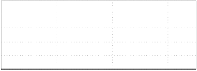
Figure 3.20: Open loop frequency response. Solid line: notch based design.
Dashed-line: phase stable design.
−110
−120
−130
−140
−150
−160
−170
10
0
10
1
10
2
10
3
10
4
10
5
10
6
200
100
0
10
0
10
1
10
2
10
3
10
4
10
5
10
6
Frequency (rad/s)
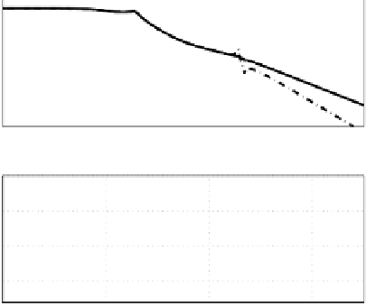
Figure 3.21: The Bode plot of the controller corresponding to Figure 3.20.
Solid line: notch based design. Dashed-line: phase stable design.
Bode plots of the open loop transfer function L(s), controller transfer func-
tion C(s), senitivity transfer function S(s) and shock transfer function S
h
(s)