Geoscience Reference
In-Depth Information
Offset (m)
Receiver
REF
200
-3
0
0
-200
-100
0
100
300
P
0
Source
100
Down-going energy
IR1 at 0.19 s
L1
200
IR4 at 0.28 s
L2
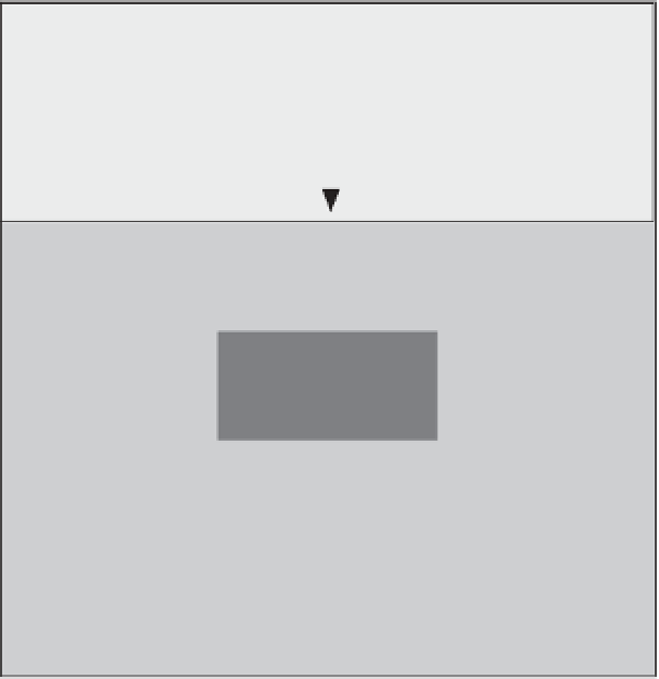
Figure 4.10
Sketch of the model used for
the simulations. The geophones and the
electrodes are collocated at the top surface
of the system. All the electrodes are
assumed to be connected to a reference
electrode. REF corresponds to the position
of the reference electrode. L1 and L2
correspond to the two layers of sediments,
and R stands for the reservoir. Arrows
indicate ray paths for seismic energy that
creates the seismoelectric interface
response labeled IRi. In addition to this
signal, the direct field and reflected seismic
arrivals are recorded as the coseismic
electric field. The seismic source is located
at a depth of 20 m below the top surface.
IR2 at 0.24 s
Relection
300
IR5 at 0.30 s
R
400
Relection
IR3 at 0.27 s
500
600
Table 4.3
True values of the material properties used for
the synthetic model shown in Figure 4.10.
RCS1, RCS2, and RCS3, respectively. A coseismic signal
occurs when a seismic wave travels through a porous
material, creating a relative displacement between the
pore water and the solid phase. The associated current
density is balanced by a conduction current density.
It results in an electrical field traveling at the same speed
as the seismic wave. Because shear waves are isochoric,
they are not responsible for any source current density
in a homogeneous medium, and therefore, they have
no coseismic electric field associated with them (Haines
& Pride, 2006).
The second type of seismoelectric signal corresponds to
converted seismoelectric signals associated with the
arrival of the P-waves at each interface (between the
two layers and at the surface of the reservoir). These con-
verted seismoelectric signals are labeled IR1, IR2, IR3,
IR4, and IR5 (see Figures 4.10, 4.11, and 4.12). When
crossing an interface between two domains characterized
by different properties, a seismic wave generates a
time-varying charge separation, which acts like a dipole
that radiates electromagnetic energy. In our approach,
we neglect the time used by this electromagnetic energy
to diffuse from the geological
Parameter
Units
Unit L1
Unit L2
Unit R
m
2
10
−
12
10
−
16
10
−
11
k
0
ϕ
—
0.25
0.10
0.33
K
s
GPa
36.50
6.90
37.00
K
f
GPa
0.25
0.25
2.40
K
fr
GPa
2.22
6.89
9.60
G
GPa
4.00
3.57
5.00
kgm
−
3
ρ
s
2650
2650
2650
kgm
−
3
ρ
f
1040
1040
983
1 × 10
−
3
1 × 10
−
3
8 × 10
−
1
η
f
Pa s
Sm
−
1
σ
0.01
0.1
0.001
Log C m
−
3
0.203
3.49
3.2
log
Q
V
L1 and L2 stand for the two layers and R for the reservoir. Layer L1
correspondstoaclean sand, L2 to a clayey sand, and R to a sand
reservoir partiallyfilled with oil.
CS. Other coseismic signals are associated with the
reflected P-waves at
the various interfaces like the
L1
-
L2 interface, the L2
-
reservoir interface, and the res-
ervoir
-
L2 interface. These coseismic signals are labeled
interface, where it is