Biomedical Engineering Reference
In-Depth Information
HI
. . .
Hj
RI
Rk
. . .
. . .
controlling tension
controlling pressure
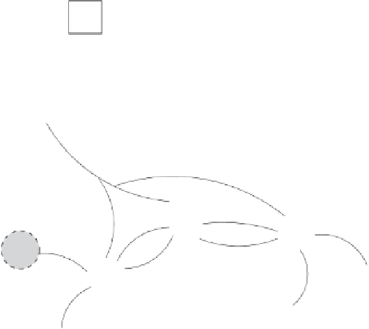
Fig. 8.2.
A schematic illustration of the connection between excitable units in the
nuclei HVC and RA. Inhibitory neurons are represented by squares, and excitatory
neurons are represented by
circles
. HVC units are
white
, and RA units are
shaded
gray
.
Square
and
round
connections represent inhibitory and excitatory connections,
respectively. For the sake of clarity, only a few representative units and connections
are shown
be attempted, using the architecture shown in Fig. 8.2. What equations allow
us to “translate this picture into a computational model”?
8.4.1 Simulating the Activity of HVC Neurons
In order to generate Fig. 8.3, we integrated conductance-based equations for
the membrane voltages of HVC and RA neurons. In this and the following
subsections, we write these equations down. The arrangements of neurons
used to emulate the behavior of the nuclei are much simplified. However, this
simplification will give us an insight into the way to proceed in order to carry
out this kind of simulation.
We write the equations for a set of
N
HV C
HVC
RA projection neurons,
denoting the time-dependent membrane potential for the
j
th HVC excita-
tory neuron by
V
Hj
,where
j
=1
,
2
,...,N
HV C
. This potential satisfies the
→