Environmental Engineering Reference
In-Depth Information
The system is designed to maximize the power output capability of an
installation. To this end, the efficiency of the turbine, the available hydraulic
head, and the flow capability of the well are maximized. To calculate the
power output during the generation cycle, the basic fluid power Equation
(4.1) applies.
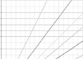
Figure 4.3 plots various hydraulic head values on a power versus flow
plane, assuming a turbine efficiency of 70%. The calculation was performed
using metric units and the results were converted to English units. The plot
shows that power output is maximized when hydraulic head and flow are
also maximized. While the head is generally dictated by the characteristics
of the installation site, the flow parameter can potentially be increased, as
discussed in the following sections.
In addition to power output, it is desirable to maximize the energy output
delivered by the system. Energy storage capacity is determined by the vol-
ume of stored water and the rated power (head, flow, and efficiency) of the
system:
Energy [kWh] = Power [kW] ∙ Time [h]
(4.2)
It is desirable to maximize hydraulic head to achieve the maximum possible
energy output. Flow and reservoir volume are closely coupled parameters
that affect the energy capacity and are constrained by the required duration
Pumped Hydro Turbine Power Output, E�ciency = 70%
3000 ft
(914 m)
2000 ft
(609 m)
1500 ft
(457 m)
1250 ft
(381 m)
1000 ft
(305 m)
400.0
375.0
350.0
325.0
750 ft
(229 m)
300.0
275.0
250.0
225.0
500 ft
(152 m)
200.0
175.0
150.0
125.0
250 ft
(76 m)
100.0
75.0
50.0
100 ft (30.5m)
50 ft (15.2 m)
[gal/min]
Flow
[m
3
/sec]
25.0
0.0
FIGURE 4.3
Relationship of power to flow and hydraulic head.