Biomedical Engineering Reference
In-Depth Information
was generated around the root of the tooth with an average thickness of 0.2 mm. The entire model
of maxillary bone is shown in Figure 20.1, and a bone segment including the PDL and central inci-
sor is shown in Figure 20.2. The commercial CAD software SolidWorks 2007 (SolidWork Corp.,
Dassault Systemes, Concord, MA) was used to build the orthodontic bracket, arch wire, and dental
implants. According to the Straumann Standard Plus Implant System, the cylindrical implant used was
10 mm long with a diameter of 4.1 mm (Φ 4.8 mm Regular Neck, RN) and a neck height of 1.8 mm
z
z
x
y
x
(a)
(b)
y
z
x
y
(c)
(d)
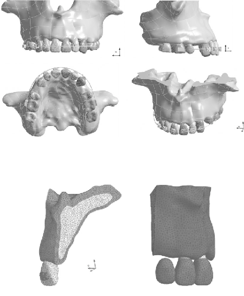
FIgure 20.1
For orthodontic treatment, a geometric model of maxillary bone was built including the
cortical bone, trabecular bone, teeth, PDL, bracket, and arch wire. (a) Frontal view, (b) side view, (c) bottom
view, and (d) isometric view.
Distal
Mesial
z
x
y
(a)
(b)
FIgure 20.2
(a) An FE model of maxillary bone segment (including the central incisor, PDL, and bracket)
used in the simulation of orthodontic tooth movement; (b) an FE model of a portion of the maxilla with
cantilever bridgework connecting two implants.
Search WWH ::

Custom Search