Graphics Reference
In-Depth Information
Synchronous Modeling Commands
NX allows you to modify the part geometry instantaneously using the Synchronous Model-
ing commands. These commands help you to move, rotate, copy, replace, and offset faces. In
addition, you can define relations and dimensions between the faces of the model geometry.
The following sections explain various Synchronous Modeling commands.
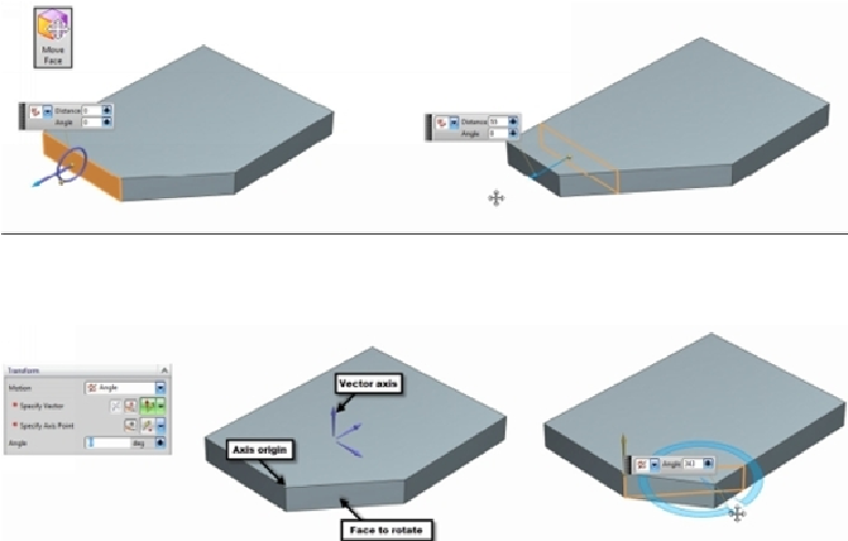
Move Face
This command moves a set of faces and adjusts the side faces to accommodate changes.
Activate the
Move Face
command (on the ribbon, click
Home > Synchronous Modeling
> Move face
) and select a face. Drag the arrow that appears on the selected face, and then
release the pointer to define the distance. You can also type-in a value in the
Distan
ce box.
To rotate a face, select
Transform > Motion > Angle
on the
Move Face
dialog, and then
select a vector axis. Click on a vertex to define the origin of the vector axis. Select the face
to rotate and drag the angle handle.
Use the
Cut and Paste
option to cut and paste a model face. To do this, click on a model
face, and then select
Settings > Move Behavior > Cut and Paste
on the
Move Face
dialog.
Now, select
Transform > Motion > Distance
, and then select a vector axis to define the
moving direction. Under the
Settings
section, check the
Heal
and
Paste
options, and then
drag the arrow that appears on the selected face.