Biomedical Engineering Reference
In-Depth Information
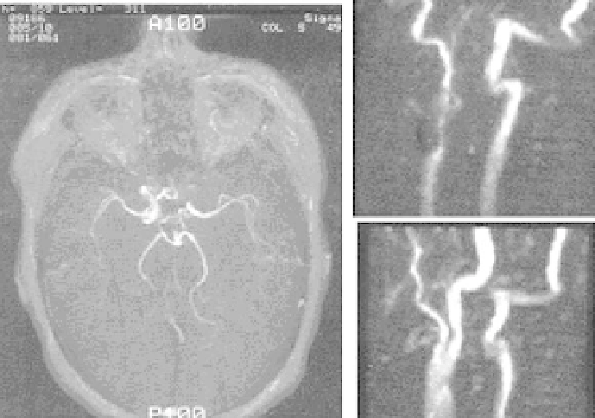
Figure 3.11: Three-dimensional TOF angiogram showing circle of Willis con-
firming the occlusion of the left internal carotid artery (left panel). Two-
dimensional TOF angiograms demonstrating an internal carotid artery occlu-
sion. A sagittal projection of right carotid bifurcation reveals a patent vessel post
endarterectomy (top row on right). The sagittal projection of the left carotid bi-
furcation reveals stenosis of the proximal external carotid artery and occlusion
of the internal carotid artery (bottom row on right).
and imaging time, 128
×
128, 192
×
256, or 256
×
256 matrix can be used with
NEX
=
1. Very short echo times may be attained with flow compensation. These
optimized scan parameters permit adequate penetration of inflowing, fresh, fully
magnetized spins into the imaging volume. The resultant 3D data set initially is
displayed as a series of slices, acquired in the axial plane. Later, it is subjected
to the MIP ray tracing technique to create coronal and sagittal projections. A
series of projections may also be generated to “rotate” the vascular structures
around a single axis. Cine loop display can provide the perception of depth.
Advantages of 3D techniques are appreciable as these techniques are more sus-
ceptible to saturation effects and less sensitive to slow flow. Thus, 3D volume
acquisition techniques offer superior signal-to-noise ratios (SNR). 3D TOF MRA
offers a prescription of very thin slices, thereby reducing the voxel size and
decreasing the intravoxel dephasing. 3D TOF MRA maximizes the flow-related
enhancement.