Civil Engineering Reference
In-Depth Information
Thus, assuming a fixed-fixed end with no buckling, the thermal stress developed
in the element is given by
T
i
m
−
T
i
−
1
σ
TE
=
1,000
(
E
)(
CTE
)
[
=
]MPa
(6.89)
m
This thermal stress is applied to the element during each time step such that the
effects of thermal expansion are incorporated.
6.3.3 Model Results
The model simulation results are presented in this section for Parameter Set 4
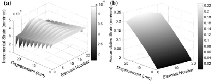
using the derived EAF thermo-mechanical model. The incremental strain (left) and
accumulative strain (right) are given in Fig.
6.39
.
As shown, the incremental strains are greater for elements that are at higher
temperatures as compared to the elements with lower temperatures. The accumula-
tive strain increases with time, and the elements in the center have a greater overall
strain due to the elements having greater temperatures.
From the accumulative strains, the element length and element areas are cal-
culated. These results are presented in Fig.
6.40
, where increased element length
results in a smaller cross-sectional area.
As a result of the EAF multi-physics model incorporating a thermal aspect, the
temperature distribution is calculated at each time step. The temperature distribu-
tion is given on the left of Fig.
6.41
, and the maximum temperature with respect
to time from the model and experimental results is displayed on the right of
Fig.
6.41
.
As seen, the thermal response increases during the application of the electri-
cal current and decreases once the current is discontinued. Also, the temperature
increases over time, and the element with the most strain (i.e., center element) is at
Fig. 6.39
Incremental strain (
left
) and accumulative strain (
right
) results from EAF multi-phys-
ics model for PS 4