Civil Engineering Reference
In-Depth Information
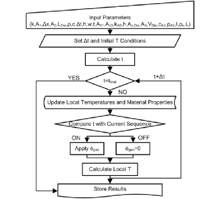
Fig. 6.2
Stationary model solution schematic [
4
]
the deformation to be uniform; therefore, the elements in the test region are equal
in size and change shape as deformation is imposed. The second accounts for dif-
fuse necking (i.e., non-uniform deformation) during forming, and in this section,
the diffuse neck is predicted using circle grid analysis (CGA) results obtained from
experimentation. The diffuse model was created as in prior EAF testing, a diffuse
neck was found to be apparent during uniaxial tension [
5
,
6
].
For the case with uniform deformation, there are several variables that do not
remain constant as in the case of stationary testing. The factors that had to be
accounted for were the shape change of the elements in the testing region of the
sheet and the heat generation per unit volume as a result of specimen shape change
[note: it is a function of sheet width and thickness as described in Eq. (
6.16
)].
The deformation in the length direction of the specimen
(
s
)
can be calculated
as follows:
(6.17)
s
=
ts
where
t
is the present time in the test and
s
is the platen speed.