Civil Engineering Reference
In-Depth Information
Mechanical Load
e
-
e
-
e
-
e
-
e
-
e
-
Top Die
L
c
Zone 1, R
1
L
Total
L
w
Zone 2, R
2
Workpiece
L
c
Zone 3, R
3
Bottom Die
e
-
e
-
e
-
e
-
e
-
e
-
Mechanical Load
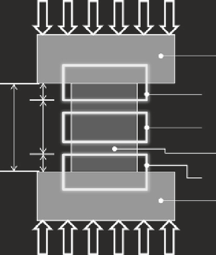
Fig. 5.7
Die and workpiece zones [
13
]. The dies/workpiece were divided into three zones where the
top
and
bottom
zones
accounted for contact area/interface obstacles, while the
center zone
did not
• The workpiece and dies are divided into three zones, as shown in Fig.
5.7
, where:
- Zone 1 is equivalent to Zone 3.
- The real contact area
<
80 % of the apparent contact area for Zones 1 and 3
and has a length of
L
c
, which depends on the surface aspect (asperity peaks).
- The real contact area is equal to the apparent contact area in Zone 2.
• One voltage value is used in the thermal/mechanical calculations, but it is com-
prised of proportioned voltages from each zone (
V
z
1
,
V
z
2
, and
V
z
3
), as shown below.
The value used for
L
c
in Eq. (
5.22
) was 1.27 mm. This was about 20 % of the total
specimen height. This was an estimation based on the thermal videos, where exces-
sive heating was apparent at these locations when electricity was applied.
L
c
L
Total
L
w
L
Total
L
c
L
Total
V
Total
=
·
V
Z
1
+
·
V
Z
2
+
·
V
Z
3
(5.22)
Equation (
5.22
) is a simplified approach to the more complicated problem of
thermal contact resistance. In reality, Zones 1 and 3 are regions where the cur-
rent flow between the dies and specimen is constricted to the narrow intermetallic
contacts. A thermal contact resistance calculation should include the resistance of