Civil Engineering Reference
In-Depth Information
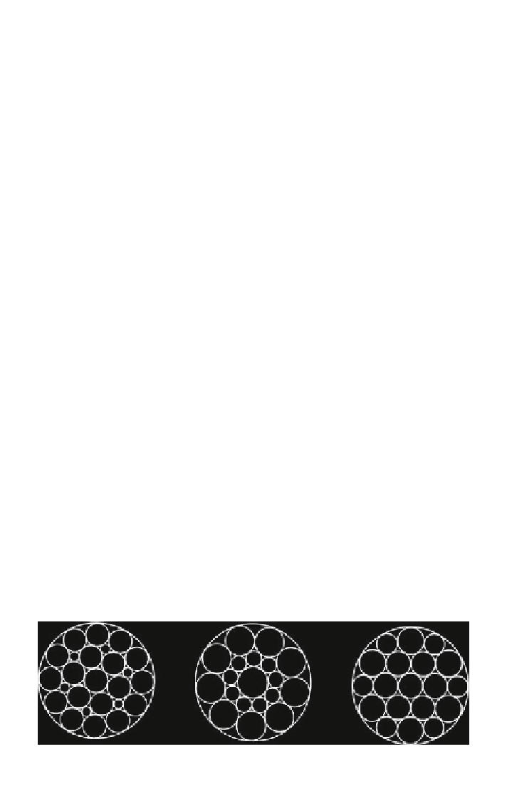
1 + 6 + 12
1 + 6 + 12 + 18
Fig. 1.22
Cross lay strands (multiple operation lay)
Cross lay strands. In the so-called cross lay strands (symbol M), the wires in the
different layers do not have the same lay length. Therefore the wires of the layers
cross each other. The cross lay strands normally have the same lay angle and the
same lay direction for all layers. As they all have the same lay angle, in principle
the wires of all layers transfer the same tensile stress. The advantage gained by
having the same tensile stress has less influence than the disadvantage arising from
the pressure between the crossing wires. Therefore wire ropes with cross lay
strands are seldom used. The cross-section of both of the cross lay strands still
used -1 + 6 + 12 = 19 M and 1 + 6 + 12 + 18 = 37 M—are shown in
Fig.
1.22
. Apart from the centre wire, which is slightly thicker, all other wires have
the same diameter.
Parallel lay strands. In parallel lay strands, the lay length of all the wire layers is
equal and the wires of any two superimposed layers are parallel, resulting in linear
contact. The wire of the outer layer is supported by two wires of the inner layer.
These wires are neighbours along the whole length of the strand. Parallel lay
strands are made in one operation. The endurance of wire ropes with this kind of
strand is always greater than of those with cross lay strands.
Parallel lay strands with two wire layers have the construction Filler, Seale or
Warrington. The cross-section of this type strand is shown in Fig.
1.23
in the most
frequently used version with 19 wires—not counting the six very thin Filler wires.
Filler strand
(symbol F)
Seale strand
Warrington strand
(symbol S)
(symbol W)
Fig. 1.23
Parallel lay strands with two wire layers

Search WWH ::

Custom Search