Civil Engineering Reference
In-Depth Information
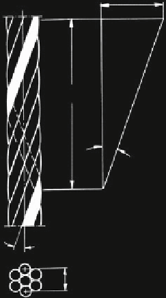
Fig. 1.20
Simple strand
2r
w
ˀ
h
w
ʱ
ʱ
2r
w
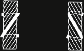
Fig. 1.21 Lay direction of
wires in a strand
lay direction right
symbol z
lay direction left
symbol s
around a centre wire. Such a strand with six outside wires around a centre wire is
shown in Fig.
1.20
.
In Fig.
1.20
the important values are clearly defined: the wire lay length h
W
, the
lay angle a and the wire winding radius r
W
. The wire lay length h
W
is the length of
the strand in which an lay wire makes one complete turn. The wire lay angle a is
given by the equation
tan a
¼
2
p
r
W
h
W
:
ð
1
:
4
Þ
The lay direction of the lay wires in the strand can be right (symbol z) or left
(symbol s). Figure
1.21
illustrates the origin of these symbols. Strands with more
than one wire layer have very different constructions.

Search WWH ::

Custom Search