Civil Engineering Reference
In-Depth Information
140
x10
3
120
60
r
˕
100
r=0,53d=3,2mm
80
60
Seale 8 x 19 - NFC - sZ
nominal diameter
40
d = 6 mm
R
2
= 1370/1770 N/mm
2
nominal strength
20
sheave diameter
D = 86 mm
tensile force
S = 2.25 kN
0
0
20
40
60
80
100
120
140
160
180
deflection angle
ˑ
D
0
0,5
1,0
1,5
2,0
2,5
3,0
3,5
rope contact length / the rope lay length
Fig. 3.53
Breaking number of bending cycles of a rope for different deflection angles, Müller
(
1961
)
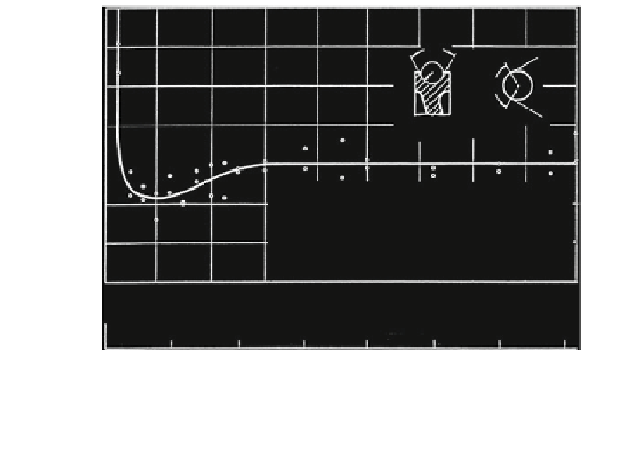
3.2.3.9 Side Deflection of the Rope
It has been well-known for a long time that the side deflection of the rope from the
sheave groove reduces the number of rope bending cycles. Therefore the technical
rules prescribe the limits of 4 for the angle to be allowed for the stranded ropes
and 1.5 for non-rotating and low-rotating ropes.
Matthias (
1966
,
1970
) has described the contact form of a side-deflected wire
rope on the groove flank. The first systematic bending fatigue tests with a different
side deflection for the rope were carried out by Neumann (
1987
). Figure
3.54
shows as his results the discard number of bending cycles for side deflection angles
between
#
= w = 0 and 4.
Schönherr (
2005
) researched the influence of the side deflection on the breaking
number of bending cycles between the side deflection angle w = 0 and 7 in a
great number of bending fatigue tests. The tests were carried out on six ordinary
lay ropes and multi-strand ropes. The diameter ratio was D/d = 12.5 and 25 and
the specific tensile force varied between S/d
2
= 58-312 N
/
mm
2
. As an example,
Fig.
3.55
shows the breaking number of bending cycles N and N
10
of a multi-
strand rope, with the side deflection in the same (+ sign) or in the opposite (- sign)
direction to the lay direction of the outside strands. All the results show that the
groove opening angle between c = 30 and 60 has no influence on the number of
rope bending cycles.

Search WWH ::

Custom Search