Civil Engineering Reference
In-Depth Information
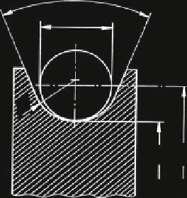
Fig. 3.33
Sheave with round
ʳ
groove
d
D
0
D
based on the actual or nominal values of a rope cross-section or rope diameter. For
detecting the influence of wire stresses, the real dimensions have to be used. How-
ever, for practical endurance tests, test results related to the nominal rope cross-
section or the nominal rope diameter are to be preferred because the user normally
only knows the nominal values. Moreover, this has the advantage that the deviation
of the actual to the nominal rope cross-section and rope diameter is included in the
standard deviation of the test results. In the following, the test results are normally
related to the specific tensile force S/d
2
with the nominal rope diameter d.
The wire rope and its lubrication have to be defined precisely, Table
3.2
. In the
following bending tests described here, the wire ropes are normally well lubricated.
For the tests in the Stuttgart Institute, usually a viscous mineral oil was used as a
lubricant, without additives and with a viscosity of 1,370-1,520 mm
2
/s for 40 C.
The sheave diameter D means the distance from rope centre to rope centre as
shown in Fig.
3.33
. The diameter ratio D/d is normally related to the nominal rope
diameter. If not defined otherwise, the sheave is made of steel with a hardened
round groove, a groove radius r = 0.53d (nominal rope diameter) and a groove
opening angle c = 60.
The bending test is completed when the rope or at least one strand is broken so
that the bending test cannot be continued. The number of rope bending cycles
achieved is the so-called breaking number of bending cycles N. In most cases, the
number of bending cycles is recorded as well when a discarding criterion such as
the discarding number of wire breaks B is detected. This number of bending cycles
is called the discarding number of bending cycles N
A
.
During a wire rope bending test, the rope-bending machine is stopped several
times so that the state of the rope bending zones can be inspected. Any change in
the rope bending zones is then recorded, in particular the number of wire breaks is
counted and the rope diameter measured. The number of bending cycles at which
the machine has to be stopped (by the counting device for the machine revolutions)
is normally taken from the Renard row R10. The numbers in this row are: 100,
125, 160, 200, 250, 315, 400, 500, 630, 800, 1,000 multiplied by 10
x
, where x is a
whole number.
Search WWH ::

Custom Search