Civil Engineering Reference
In-Depth Information
The number of wire breaks B and, in some special cases, the rope diameter d as
a function of the number of bending cycles found during the bending tests is used
twice. First of all, for all tests with ropes of the same construction, the number of
wire breaks B
A
is evaluated to find out if the wire rope should be discarded. The
basis for this evaluation is the number of wire breaks B found at 80 % of the
breaking number of bending cycles N. Secondly, the discarding number of bending
cycles N
A
can be recorded based on the number of wire breaks B
A
obtained during
the rope-bending test.
3.2.2 Number of Bending Cycles
3.2.2.1 Tensile Force and Diameter Ratio
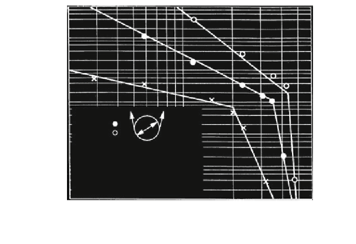
The most important influences on the number of bending cycles are the rope
tensile force S and the diameter ratio D/d (sheave to rope diameter). In Fig.
3.34
,
these influences on the breaking number of bending cycles (simple bending cycles)
are shown for a Filler rope 8 9 (19 + 6F) - NFC - sZ. The breaking number of
bending cycles and the specific rope tensile force are drawn in logarithm scale.
In this diagram form the numbers of bending cycles from the tests form very well
represented by straight lines for constant diameter ratios D/d.
At a certain high tensile force, the number of bending cycles drops abruptly.
The limit of the tensile force where the number of bending cycles begins to drop is
10
7
10
6
10
5
10
4
D/d = 10 x
25
63
D
10
3
Steel hardened, r = 0.53 d
Filler 8x(19+6F)-NFC-B-sZ
R
m
= 1650 N/mm
2
, d = 16 mm
10
2
4
lubricated before test, mineral-oil
2
10
visc. 1370 - 1520 mm
2
/s (40 C)
100 N/mm
2
600
20
30
40 50 70
specific tensile force S/d
2
300
400
200
Fig. 3.34
Breaking numbers of bending cycles for one Filler rope

Search WWH ::

Custom Search