Civil Engineering Reference
In-Depth Information
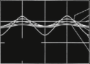
Fig. 3.2 Wire bending stress
in a strand between straight
and bent, Schiffner (
1986
)
1.5
Bock
Czitary
Reuleaux
1.0
Costello
Leider
= 1.4 mm
r
w
= 2 mm
D = 1000 mm
0.5
(
˕
=konst.)
Schiffner
(
= 20
ʱ
=konst.)
0
ʠ
3
0
ʠ
ʠ
2
ʠ
2
winding angle
˕
to be used. The bending stress and the torsion stress can be calculated for the
difference in the space curve of the wires before and after the rope is bent by using
Figure
3.2
shows the difference between the bending stresses found in a wire
for the bent and the straight strand which some authors have calculated. In the case
of a constant ratio between the winding angles, the correct bending stress comes
from Leider (
1977
) and in the case of a constant lay angle, the correct bending
stress comes from Schiffner (
1986
). Costello (
1977
) describes the bending stress,
when the wire helix is not supported by a centre.
Schiffner (
1986
) shows that the space curve with a constant lay angle has the
smallest distance between two points over a bent cylinder, the wire will not be
stressed by torsion and the bending stress is smaller than in the case of a constant
ratio of the winding angles. However, in contrast to wires with a constant ratio of
the winding angles and compared with the straight helix, the bent wire helix with a
constant lay angle needs additional lateral space.
Therefore a constant ratio of the winding angles occurs in modern strands
where there is not much clearance between the neighbouring wires.
3.1.1.3 Bending of a Stranded Rope
Schiffner (
1986
), whose work is related to that of Paetzel (
1969
) and Wiek
(1975)—and later on independently Hobbs and Nabijou (
1995
)—was the first to
present the equations for the space curve of the wires in the bent stranded rope. He
has also shown that it is not possible for the ratio of the winding angles around the
strand axis and the rope axis and, on the other hand, the ratio of the winding angles
around the rope axis and the sheave axis to be constant at the same time. He found
that it can be either
D
#
Du
S
Du
S
Du
W
¼ const
:
and
6
¼ const
:


Search WWH ::

Custom Search