Information Technology Reference
In-Depth Information
50
1 v(21)
0
-50
-100
0
20
40
60
80
100
ms
Fig. A.22
Enabled Logic Inputs
0
-10
-20
-30
-40
-50
v(5)
-60
v(10)
-70
-80
0
20
40
60
80
100
ms
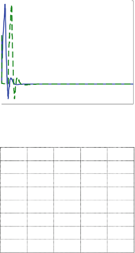
Fig. A.23
One input applied at 10 us, 100 pF at v(5), no output at v(10)
Fig.
A.22
illustrates the pulses to be used as inputs. Fig.
A.23
shows that
one input produces no output (V10). Fig.
A.24
shows that two inputs produce an
output (V10).
• What is the permitted time spread, approximately, between inputs?
• How much can capacitance C
1
vary and still produce the AND effect?


Search WWH ::

Custom Search