Biomedical Engineering Reference
In-Depth Information
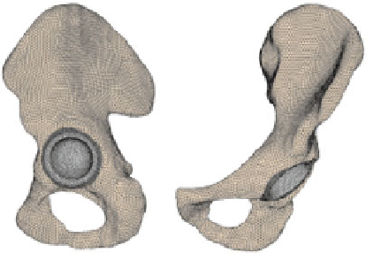
Fig. 1
FE-model of the
periprosthetic pelvis and
components of the calculated
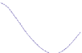
resultant hip joint forces [
17
]
FE model of the prosthetic pelvis
Boundary conditions
bone
cement
cup
F
res
z
y
x
2500
F
x
F
y
F
z
2000
1500
1000
500
0
-500
-1000
-1500
0
20
40
60
80
100
percentage of gait [%]
simulated on the basis of the established simulation method [
16
,
17
]. In Fig.
1
the
FE-model of this simulation is illustrated, consisting of the bony structure provided
with a cemented cup. In addition to the FE-model the components of the calculated
resultant hip joint forces used as boundary conditions are pictured in Fig.
1
.Forthe
determination of hip joint forces anMBS model of a human test person with a normal
walking speed (1
1m/s) was used.
According to the simulation with load conditions derived from the MBS a total
bone loss of 1
.
4% can be assumed in the periprosthetic pelvis. The density distribu-
tions in the periprosthetic pelvis for the initial and final state are illustrated in Fig.
2
.
A high bone resorption can be observed in the acetabulum. On the basis of the final
density distribution in the acetabulum a migration of the conventional cup can be
suggested in proximal direction.
This migration can be avoided by means of patient-individual hip cups. In the
following section a new concept for the design and production of patient-individual
hip-cups prostheses out of titanium sheets will be introduced and the results of the
concept development will be presented.
.