Biomedical Engineering Reference
In-Depth Information
Figure
4
exemplary shows the inhomogeneous strain distribution in two cross
sections. Additionally, the normalized distribution of all strains is plotted. Two peaks
arise in the distribution, that represent the different strain levels of both materials.
The macroscopic obtained strain, however, lays in between.
2.4 Window Size and Boundary Conditions
Three boundary conditions in terms of displacement or stress can be defined on each
surface of the RVE, compare Figs.
5
and
6
.
The Hill condition demands a compatibility of strain and (!) stress, which would
require a definition of six boundary conditions on each surface, meaning that three
strain and three stress components have to be applied. Consequently, the Hill condi-
tion cannot be completely fulfilled for boundary value problems like the FEM. The
obligatory chosen conditions have a strong influence on the stiffness estimation. The
structure is estimated too stiff, if pure displacement conditions are applied. Con-
trary to this, the structure is estimated too soft, if pure stress conditions are applied.
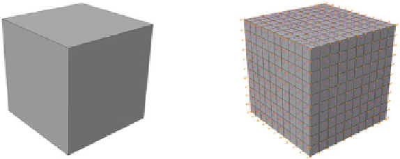
Fig. 5
Left
Definitions of RVE surfaces.
Right
FEM visualization
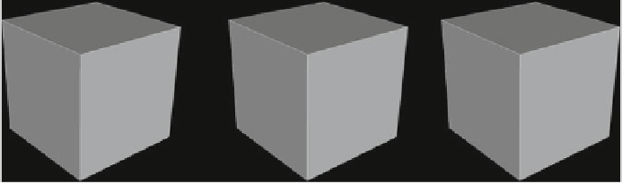
Fig. 6
Boundary condition sets.
Left
Pure kinematic constraints.
Middle
Mixed constraints
proposed by Pahr and Zysset [
8
].
Right
Pure stress constraints