Biomedical Engineering Reference
In-Depth Information
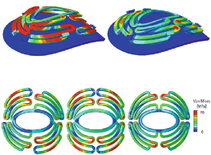
(a)
(b)
Fig. 11
View of myocardium with standard scaffold in end systolic state:
a
0.5mm thick scaffold;
b
1mm thick scaffold
(a)
(b)
(c)
Fig. 12
Shape improvements and variants of standard scaffold
scaffold shape to achieve adequate stress distribution without fundamental design
changes.
The scaffold shape in Fig.
13
a was designed and simulated with the previously
described modeling approach. The corner of the highlighted arm was structured
with tensile triangles that had changed dimensions. It can be seen that the stress
distribution is getting smoother from b to e in Fig.
13
. Also, the maximal stress is
decreased by about 11% from b to e. This was achieved by increasing the basic
length of the tensile triangles from 5mm to 9mm, and as a result the entire rounding
grew. For this reason, the application of tensile triangles is a good option to reduce
stresses in complex structures as well. It is only limited by the available space.
Only the shapes 1, 2, 6, 9, 10 and 12 in Fig.
14
are free of plastic strains. Out of
these, shape 6 and shape 9 are the most promising, with maximal stresses of 90MPa
and 120MPa, respectively. Further, the stress distribution is smoother in these designs
as compared with the other shapes.
4 Summary and Discussion
Loss of myocardial tissue due to ischemic incidents results in reduced heart per-
formance. Innovative biological grafts can be used to replace lesioned tissues [
7
].
Furthermore, their recolonization with cardiomyocytes gives evidence supporting