Biomedical Engineering Reference
In-Depth Information
3.2 Results for Shape Improvements and New Designs
Extending the simulation and adding pressure onto the back of the scaffold in systolic
step had an impact on results. Stresses in the diastolic step were still the same as
presented in Fig.
6
, but stresses in the systolic step increased significantly, as can be
seen in Fig.
10
. The 1mm thick scaffold had a maximum stress of 164MPa, while
the maximal von Mises stress of the 0.5mm implant was determined to be 199MPa.
For both scaffolds, plastic strains occurred in end systolic state.
Including a systolic pressure had a more profound influence on the thinner scaf-
fold; its lower stiffness caused greater deformations. This can be seen in Fig.
11
,
where the 0.5mm scaffold is lifted from the myocardium. The 1mm thick scaffold
is less affected by the systolic pressure and had only minor lifting. Nevertheless, its
maximal stress with 164MPa was about 70% higher in comparison with the model
without a systolic pressure. Further, the stress distribution changed, as can be seen
in Figs.
6
and
10
. Consequently, modeling of a systolic pressure was included in all
following calculations to cover bulging grafts.
With the broadening of narrow radii, a slight decrease in maximal stress was
reached but the highest stresses were still achieved at the inner tight radii, as pictured
in Fig.
12
. In contrast to the standard scaffold, no plastic strains were observed.
Keeping the design requirements in mind, it seems impossible to adjust the standard
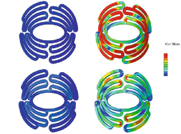
Fig. 10
Stress distribution in end diastolic and in end systolic state for 0.5 and 1mm thick standard
scaffolds after including a systolic pressure