Environmental Engineering Reference
In-Depth Information
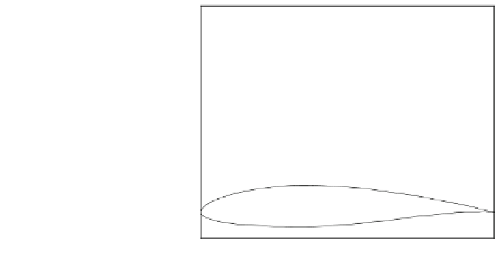
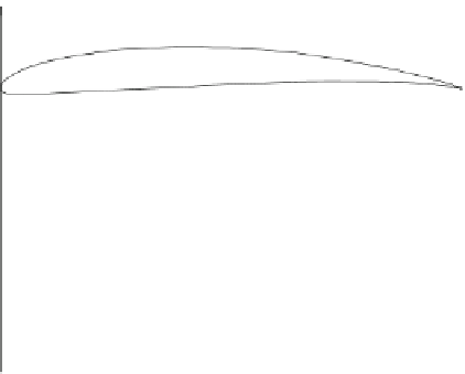
Fig. 4.2 The SG family of
aerofoils for small wind
turbines. The straight line is
the chord line. The camber
and thickness are in Table
4.1
0.8
0.7
6043
0.6
0.5
6042
0.4
0.3
6041
0.2
0.1
0
6040
-0.1
0
0.2
0.4
0.6
0.8
1
Distance along chord line, x/c
The first of the four numbers indicates the camber as a percentage of c; this is
zero for a symmetric section. The last aerofoil in Fig.
4.1
, the 6412, has 6%
camber, which is about the upper limit for practical aerofoils. The second number
in the aerofoil designation, 4 in every case, indicates that the camber occurs at 40%
of c. This is the position of maximum thickness for all members for the NACA
four digit family.
Figure
4.2
shows the more modern SG aerofoils designed by Professor Michael
Selig (S) and Phillipe Giguere (G) of the University of Illinios at Urbana-Champaign,
specifically for small wind turbines. They are probably the first aerofoils designed
for that purpose. Their basic geometry and design parameters are given in
Table
4.1
taken from Giguere and Selig [
3
]. Other aerofoil sections for small
turbines are described by Giguere and Selig [
4
] and Kogaki et al. [
5
].
The 16% thick SG6040 is a root aerofoil, while the other three, intended for the
power-extracting outer parts of the blade, have 10% thickness with varying
camber. Some of the important features of the design methodology will be dis-
cussed in the next section.
4.3 Aerofoil Lift and Drag
An aerofoil of a given shape will have a lift, l, and drag, d, dependent on U
0
(which
for aerofoils is equivalent to the effective velocity U
T
for blade elements), c, q, m,
and the angle of attack a. This leads to the definition of the lift and drag coeffi-
cients as:
l
d
C
l
¼
and
C
d
¼
ð
4
:
1
Þ
1
2
qU
0
c
1
2
qU
0
c


Search WWH ::

Custom Search