Environmental Engineering Reference
In-Depth Information
digit family of aerofoils was developed in the late 1920s. It has the advantage of
being analytically described, whereas most modern sections are specified by their
surface co-ordinates. The four digit family illustrates the basic terminology of
aerofoils which arose from the manually-intensive methods of wing and propeller
blade layout used in the early days of the aircraft industry.
The extreme forward point on the aerofoil is the leading edge, which is on the
left for the four aerofoils in Fig.
4.1
; the airflow is from left to right and the lift, l,
acts upwards. Virtually all aerofoils have a sharp trailing edge, at the right hand
end of the sections in Fig.
4.1
. The straight line joining the leading and trailing
edges is the chord line of length, c. The angle of attack, a, which was introduced in
the previous chapter, is measured between the free stream velocity, U
0
, and the
chord line. If U
0
were in the horizontal direction, a positive a would occur by
raising the leading edges. The chord line was normally the first quantity to be laid
out for an aircraft wing. Then the mean line, shown dashed in Fig.
4.1
, was added.
It lies mid-way (the mean position) between the upper and lower surfaces of an
aerofoil. The maximum distance between the chord line and the mean line is called
the camber. Finally, the aerofoil thickness is added. The NACA four digit aerofoils
are no longer used extensively, but the 0012 is probably the most studied aerofoil
in history, see [
1
]. As indicated by the coincidence of the mean line and chord, this
aerofoil is symmetric, so that it produces no lift at zero angle of attack. This is a
very useful property for aircraft tail fins, as well as helicopter and other blades.
The ''12'' in the designation indicates that this aerofoil, as well as the other three
shown, has a maximum thickness, t, of 12% of the chord, although some sections
specifically designed for the root areas of wind turbine blades, are thicker to
accommodate the large centrifugal and other stresses in this region.
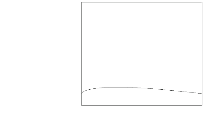
Fig. 4.1 Four examples of
the NACA 4-digit series. The
solid line denotes the surface,
the straight line is the chord
line and the dashed line is the
mean line. All aerofoils have
the same thickness (12%), but
camber increases upwards.
Each aerofoil is displaced
upwards by 0.2 units
0.8
6412
0.7
0.6
4412
0.5
0.4
2412
0.3
0.2
0.1
0012
0
-0.1
0
0.2
0.4
0.6
0.8
1
Distance along chord line, x/c


Search WWH ::

Custom Search