Environmental Engineering Reference
In-Depth Information
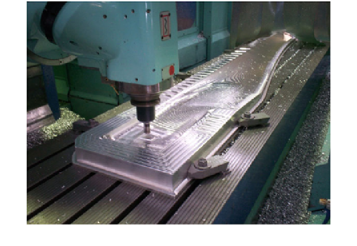
Fig. 7.10
Machining the mould for the lower surface of the 2.5 m long blade in Fig.
7.6
require adequate stiffness to avoid excessive bending under load, and a low inertia.
For large blades the latter relates to manufacturing and transport costs, whereas for
small blades low inertia is more important for starting. There is an enormous
number of manufacturing techniques available so it possible only to give a broad
and general outline. As for large blades, it is desirable to concentrate the structural
strength in a thin laminate on the blade surface. The laminate is made by
embedding reinforcing material such as fibreglass or carbon fibre within a resin.
Because of the high level of centrifugal stress, see
Sect. 1.9
, considerable rein-
forcing in the radial direction is required, often in the form of ''unidirectional''
E-glass. In addition, ''triaxial'' reinforcement in the so-called 45/90/45 direc-
tions, where 90 indicates radial reinforcement, is often used for torsional stiffness.
The reinforcement layout—the number, type of material, and its location and
extent—requires detailed FEA as demonstrated in Fig.
7.8
. In turn, the FEA must
be carefully checked as discussed in the next section.
Moulds are needed for composite blade manufacture. For large blades, these are
often made by machining thin templates which are then spaced along the span with
the gaps filled with resin and reinforcement. For small blades, dimensional
accuracy is critical, so machined moulds are often necessary. The machining of
one of the moulds for the 2.5 m long blades in Fig.
7.6
is shown in Fig.
7.10
.
Separate moulds were made for the lower and upper surface and each blade half
made by vacuum infusion, Fig.
7.11
. After the moulds are coated with a release
agent, the fibreglass is laid out by hand in the mould, covered by a ''release ply'',
a ''resin runner'', and vacuum bag. The fibreglass is not visible in Fig.
7.11
as it
Search WWH ::

Custom Search