Environmental Engineering Reference
In-Depth Information
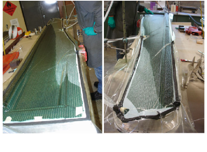
Fig. 7.11 Vacuum infusion of the lower half of a 2.5 m long blade. Left side view from hub end,
right side from the tip
and the release ply are covered by the (green) resin flow promoter which is cheap
and readily-obtainable shadecloth. The release ply is visible at the bottom of the
right hand side photograph in Fig.
7.11
. A combination of the promoter and cheap
''geocloth'' forms the resin runner along the leading edge. This promotes the rapid
flow of resin along the blade which is essential for the high aspect ratio shape. The
vacuum bag is sealed by the black sealer running around the flat landing of the
mould and the resin inlet port is just out of the left side picture on the extreme left.
The two white exit tubes are clearly seen at the top of the photograph on the left
and towards the bottom on the right side one. They are connected to a vacuum
pump which sucks the resin through the mould. The dark (green) area is the region
wetted by the resin. When the whole blade is wetted out—hopefully just before all
the resin has entered the mould—the inlet and outlet ports are pinched off and the
resin allowed to cure. It may be necessary to heat the blades halves to promote
curing.
When cured, the release ply and resin runner are peeled from the laminate. Then
the two halves must be trimmed and joined. This can be a time-consuming process
and one that must be done carefully as the blade halves will likely join at the
leading and trailing edges, which are aerodynamically important. The trailing
edge is relatively easy because the two halves present a good area for gluing, but
the laminates, which may be only 1-2 mm in thickness, meet at nearly 90 at the
leading edge. It is important to have some form of ''glue dam'' to ensure good
bonding. Measurements of the surface of a blade made by vacuum infusion are
shown in Fig.
7.12
. It is clear that the blade is too thin in comparison to the design
Search WWH ::

Custom Search